
Test fixture of light-emitting element

A technology for light-emitting components and test fixtures, which is used in optical instrument testing, machine/structural component testing, and measuring devices. The effect of preventing damage and efficient testing process

Active Publication Date: 2016-01-06
GUANGZHOU WONDFO BIOTECH
View PDF13 Cites 13 Cited by
  • Summary
  • Abstract
  • Description
  • Claims
  • Application Information

AI Technical Summary

Problems solved by technology

A common practice in the industry is to first make a PCB test board corresponding to the pad of the LED lamp, and then solder the LED lamp to the corresponding test board for circuit connection, but the high temperature during the welding process will often make the package on the surface of the LED lamp Colloids, such as epoxy glue or silica gel, will be denatured, and the discoloration will affect the corresponding optical test results of the LED
In addition, the surface-mount LED pad size is generally small. Once it is soldered to the test PCB, it is difficult to remove the LED light from the test PCB for other tests.
In addition, when testing, it is necessary to customize the corresponding test PCB board for testing a certain surface mount LED, which is time-consuming and laborious.

Method used


Image

  • Test fixture of light-emitting element
  • Test fixture of light-emitting element
  • Test fixture of light-emitting element

Examples


Embodiment 1

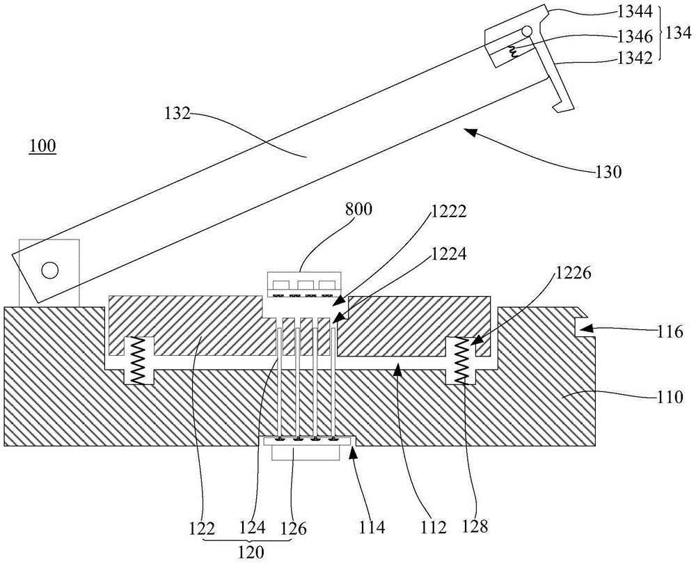
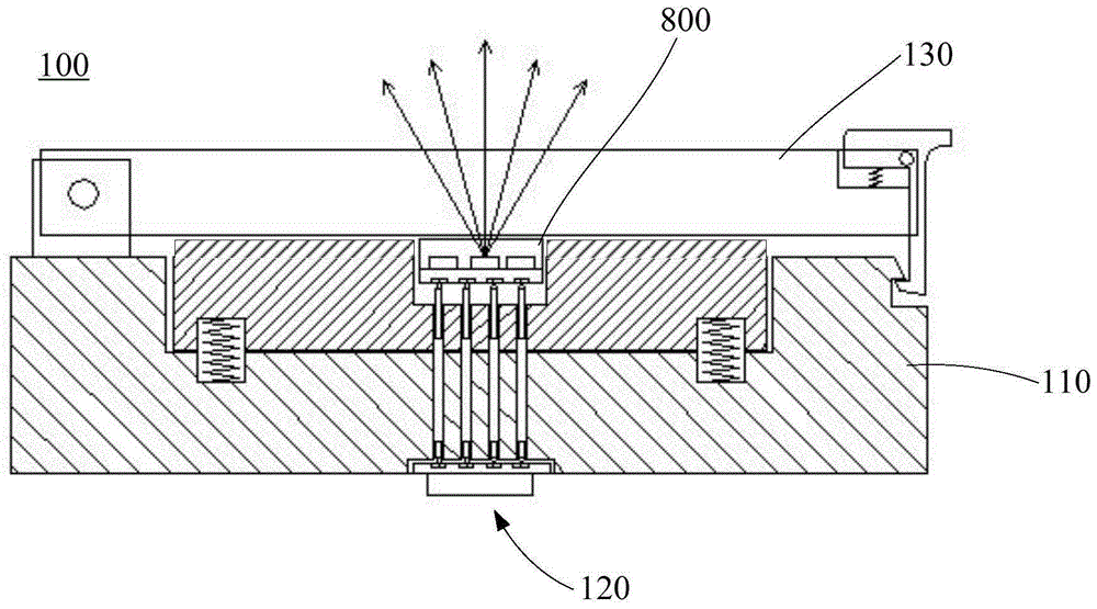
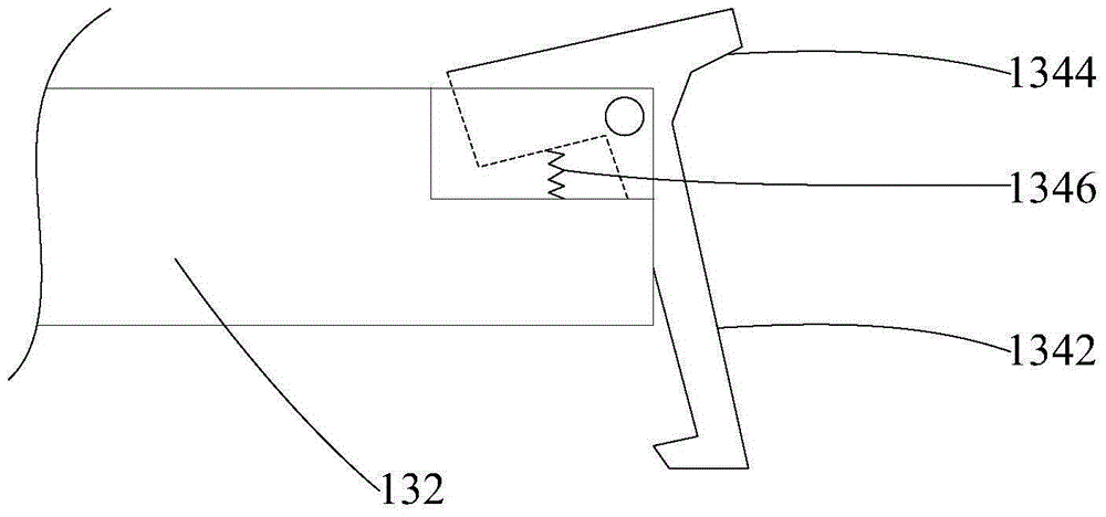
[0044] Please combine figure 1 , figure 2 with image 3, the light-emitting device testing fixture 100 of the first embodiment includes a base 110 , a testing component 120 and a limiting component 130 . The light-emitting element test fixture 100 of this embodiment is mainly used for performance testing of the light-emitting element 800 to be tested with a bottom pad, for example, performing an optical performance test on a surface-mounted LED with a bottom pad.

[0045] The upper surface of the base 110 is provided with a mounting slot 112 , and the lower surface is provided with a PCB connection position 114 .

[0046] The test assembly 120 includes a test substrate 122 , test probes 124 and a PCB test board 126 .

[0047] The test substrate 122 is disposed in the installation groove 112 . A test slot 1222 for placing the light-emitting element 800 to be tested is defined on the upper surface of the test substrate 122 . The base 110 and the test substrate 122 are prov...

Embodiment 2

[0061] Please combine Image 6 with Figure 7 , the light emitting device testing fixture 200 includes a base 210 , a testing component 220 and a limiting component 230 . The light-emitting element testing fixture 200 of the second embodiment is also mainly used for the optical performance test of the light-emitting element 800 to be tested with a bottom pad, and its structure is basically the same as that of the light-emitting element testing fixture of the first embodiment. The difference from Embodiment 1 is that the limit assembly 230 of the light-emitting element test fixture 200 in Embodiment 2 is different from the limit assembly 130 in Embodiment 1, and the structure of the corresponding base 210 and the arrangement of the test probes 224 are also different. ,details as follows:

[0062] The limiting assembly 230 of the second embodiment includes a clamping arm 232 , a clamping screw 234 and a return spring 236 .

[0063] The clamping arm 232 has a first abutting ar...

Embodiment 3

[0070] Please combine Figure 8 with Figure 9, the light-emitting device testing fixture 300 of Embodiment 3 includes a base 310 , a testing component 320 and a limiting component 330 . The light-emitting element testing fixture 300 of Embodiment 3 is mainly used for performance testing of the light-emitting element 900 to be tested with side pads, such as optical performance testing of LEDs with side pads. The structure of the light-emitting device testing fixture 300 of the third embodiment is basically the same as that of the light-emitting device testing fixture of the first embodiment. Different from the light-emitting device test fixture 100 of the first embodiment, the structures of the base 310 and the test assembly 320 of the light-emitting device test fixture of the third embodiment are different from those of the base 110 and the test assembly 120 of the first embodiment.

[0071] The test substrate 322 is provided with probe installation holes (not shown in the ...


PUM


Abstract

The invention relates to a test fixture of a light-emitting element. The test fixture comprises a pedestal, a testing assembly and a limiting assembly. The limiting assembly is used for realizing contact between a to-be-tested light-emitting element and test probes, thereby guaranteeing good contact during testing; after test completion, the to-be-tested light-emitting element can be taken from the test fixture rapidly without damaging the to-be-tested light-emitting element, so that the to-be-tested light-emitting element can be used repeatedly and other experiments are not affected and thus the whole testing process can be realized efficiently, simply and conveniently. The corresponding test assembly also can be adjusted flexibly according to different welding plate types of to-be-tested light-emitting elements; and different limiting assemblies can be modified freely under the circumstances of giving priority to the testing efficiency or giving priority to testing accuracy, thereby meeting different testing requirements.

Description

technical field [0001] The invention relates to the field of light-emitting element testing, in particular to a light-emitting element testing jig. Background technique [0002] With the development of chips and packaging technology of light-emitting elements such as LEDs, the dot pitch between light-emitting elements is getting smaller and smaller, and the pixel density per unit area is getting higher and higher. Due to the small dot pitch of high-density LED displays, in order to ensure stable product performance and facilitate manufacturing, high-density LED displays usually use surface-mounted LED lamps. Surface-mounted LED lamps often need to use optical test fixtures to test optical parameters before mounting, such as testing light intensity, dominant wavelength, light intensity distribution curve, color temperature, color coordinates, etc., to confirm the quality of the corresponding batch. Whether the LED lamps meet the requirements for manufacturing LED display scr...

Claims


Application Information

Patent Timeline
Patent Type & Authority Applications(China)
IPC IPC(8): G01M11/00
Inventor 黄仁宏陈占文胡海升罗宏王继华
Owner GUANGZHOU WONDFO BIOTECH
Learn More