
Large relative aperture near-infrared common optical path dual-field athermalized optical imaging system

An optical imaging system and relative aperture technology, which is applied in optics, optical components, installation, etc., can solve the problems of low integration of optical imaging systems, lack of passive heat dissipation, unfavorable engineering applications, etc., and achieve simple zooming methods, Excellent optical performance, compact structure effect

Inactive Publication Date: 2017-06-16
SOUTH WEST INST OF TECHN PHYSICS
View PDF4 Cites 0 Cited by
  • Summary
  • Abstract
  • Description
  • Claims
  • Application Information

AI Technical Summary

Problems solved by technology

[0004] Chinese Patent Publication No. CN102890335A discloses a digital lens optical imaging system with dual field of view star position calibration, which adopts the design type of common optical path axial movement, and realizes 70 / 200mm close to 3 x zoom ratio, with a larger rear working distance, and an F-number of 1.5, the system design band is the visible light band, but it can work in low-light conditions at night, indicating that the design can work in the near-infrared band, but the system’s 10 A total of 9 kinds of ordinary optical glass materials are used in the lens material, and there are many types of materials, and the achromatic ability of this material combination is limited, so it is difficult to apply to a wider range of wavelengths
However, the design of the optical path and focal plane of the system makes the integration of the entire optical imaging system low, and the installation and calibration are complicated, which is not conducive to engineering applications, and the optical imaging system does not have a passive adiabatic function.

Method used


Image

  • Large relative aperture near-infrared common optical path dual-field athermalized optical imaging system
  • Large relative aperture near-infrared common optical path dual-field athermalized optical imaging system
  • Large relative aperture near-infrared common optical path dual-field athermalized optical imaging system

Examples


Embodiment Construction

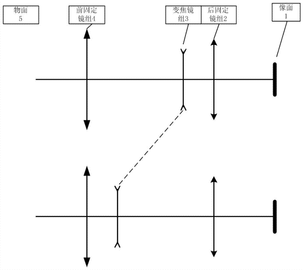
[0021] refer to figure 1 Describes the field-of-view principle of the near-infrared dual-field-of-view passive athermalization optical imaging system based on the principle of object-image exchange. The total length of the optical imaging system remains unchanged during the change of the focal length. The positions of group 2 and focal plane 1 are constant; during zooming, zoom lens group 3 moves rapidly forward and backward on the optical axis. When the field of view is narrow, the variable magnification lens group 3 moves toward the side close to the image plane 1; during the process of changing from the narrow field of view to the wide field of view, the magnification lens group 3 moves toward the side of the object plane 5.

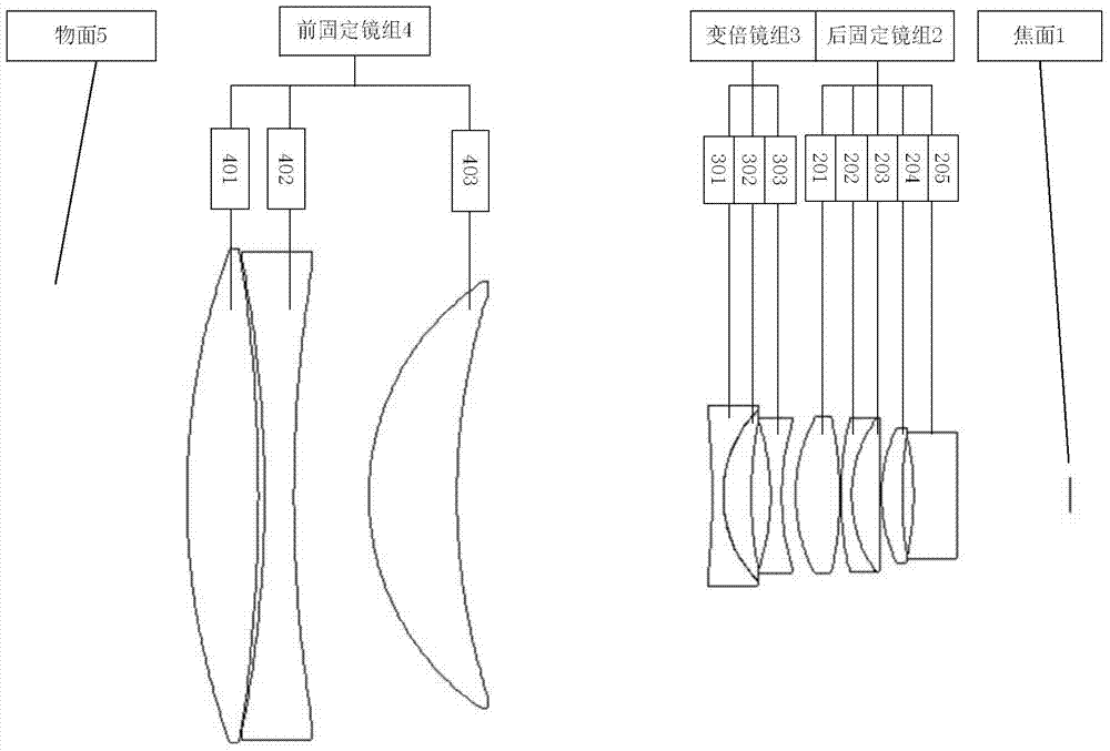
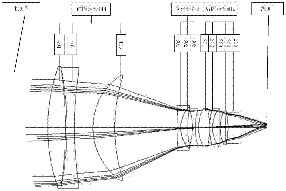
[0022] In order to eliminate thermal difference and chromatic aberration, the front fixed lens group 4 is composed of three-piece three-separated lens groups using heavy lanthanum flint glass HZLAF68B, heavy flint glass HZF88 and fluorine crown glass ...


PUM


Abstract

The invention proposes a large relative aperture near-infrared common optical path dual-field athermalization optical imaging system. The front fixed mirror group is composed of three positive, negative and positive lenses arranged and connected behind the object plane, and the rear fixed mirror group is sequentially arranged. It is composed of five positive, negative, positive, positive and negative lenses. The front fixed lens group and the rear fixed lens group are fixed during the zooming process; the middle zoom lens group is the first cemented lens made of negative and positive lenses. group and the third negative lens; the variable magnification lens group is driven by a motor fixed on the lens barrel, driven by a gear-rail mechanism, moving back and forth along the optical axis to achieve two-speed double-field zoom, and fixed with the front The mirror group and the rear fixed mirror group together constitute an optical imaging system. The present invention adopts the technology of optical athermalization difference, switches between two levels of double-field of view, and the total length of the system remains unchanged, and when imaging the same scene, it has better performance without focusing in the temperature range of -40°C to 60°C image quality.

Description

technical field [0001] The invention relates to an athermal difference dual-view field optical imaging system mainly used in the near-infrared band. Specifically, the present invention relates to a near-infrared optical imaging system that uses double-field zoom and has an optical passive adiabatic function. Background technique [0002] The near-infrared optical imaging system can reproduce most of the details of visible light images, and has better low-light night vision capabilities, cloud and smog penetration capabilities, and has a longer working distance than visible light detection. It will become a future optical imaging system. a direction of development. Ordinary optical glass materials have high transmittance in the near-infrared band, which provides great convenience for the application of low-cost near-infrared optical imaging systems, and the temperature refractive index coefficient of ordinary optical glass materials in the near-infrared band is very small, ...

Claims


Application Information

Patent Timeline
Patent Type & Authority Patents(China)
IPC IPC(8): G02B15/167G02B1/00G02B7/04
CPCG02B7/04G02B15/167G02B1/00
Inventor 袁佳邓键彭晓乐姜湖海曲锐
Owner SOUTH WEST INST OF TECHN PHYSICS
Learn More