
High-frequency filter applied to grid-connected inverter

A high-frequency filter and inverter technology, applied in the direction of single-network parallel feed arrangement, output power conversion device, electrical components, etc., can solve the problems of high-frequency current component increase, damping resistor burnout, etc., and achieve strong damping characteristics, the effect of low power consumption

Active Publication Date: 2016-01-06
BEIJING IN POWER ELECTRIC +1
View PDF5 Cites 4 Cited by
  • Summary
  • Abstract
  • Description
  • Claims
  • Application Information

AI Technical Summary

Problems solved by technology

However, the damping resistor in the RC circuit has losses, and its power depends on the average effective value of the high-frequency current. When the output current of the active filter approaches the rated value, because the inductance tends to be saturated, the high-frequency current component increases sharply. Power dissipation in damping resistors can be hundreds of watts
Therefore, we will find that when the final damage of many filters is often caused by the burning of the damping resistor

Method used


Image

  • High-frequency filter applied to grid-connected inverter
  • High-frequency filter applied to grid-connected inverter
  • High-frequency filter applied to grid-connected inverter

Examples


Embodiment Construction

[0015] The technical solution of the present invention will be further described below in conjunction with the accompanying drawings.

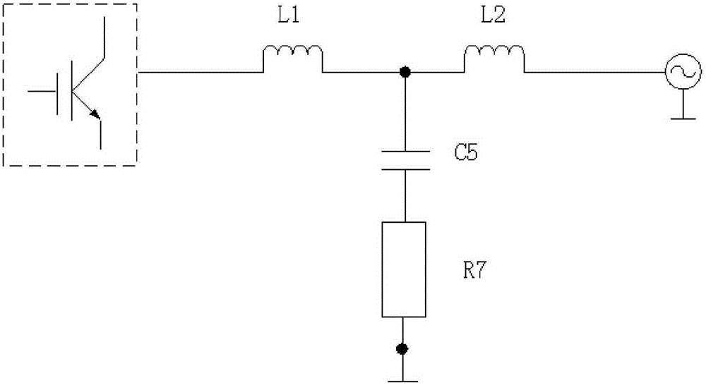
[0016] figure 1 It is the schematic diagram of the traditional LCL filter circuit. The output of the IGBT converter is connected to the inductor L1, and the output end is connected to the power grid through the inductor L2. The high-frequency components output by the IGBT bridge side are mainly bypassed to the neutral line through the RC damping branch, because The average effective value of the high-frequency component of the current is generally 10-30A, which will cause a very large loss in the damping resistor. If you want to reduce the loss, you can only make the resistance value smaller, but this will weaken the damping effect and make the system It is easier to fall into a resonance state. Therefore, the traditional LCL filter is contradictory between power consumption and stability. This problem can be improved by using the active dam...


PUM


Abstract

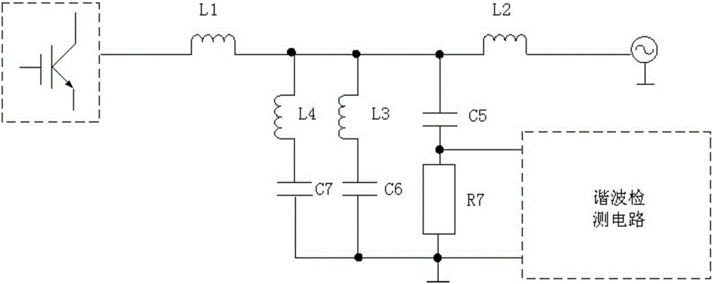
The invention relates to the field of passive filters, in particular to a high-frequency filter applied to a grid-connected inverter. The high-frequency filter comprises an IGBT converter, a first inductor (L1), a second inductor (L2) and an RC damping branch, wherein the output of the IGBT converter is connected with the first inductor (L1); an output end is connected with a power grid through the second inductor (L2); the RC damping branch comprises a fifth capacitor (C5) and a damping resistor (R7); the fifth capacitor (C5) is connected with the damping resistor (R7) in series; a high-frequency component output from a bridge side of an IGBT is by-passed on a null line through the RC damping branch; the high-frequency filter is characterized in that the RC damping branch is connected with two paths of LC tuning branches respectively composed of a fourth inductor (L4), a seventh capacitor (C7), and a third inductor (L3) and a sixth capacitor (C6) in parallel; the fourth inductor (L4) is connected with the seventh capacitor (C7) in series; and the seventh capacitor (C7) is connected with the third inductor (L3) in series. The high-frequency filter applied to the grid-connected inverter hardly generates losses; due to the value of a resonance resistor R, the damping action of a resonance point position is the strongest; the system has relatively high damping characteristics; and the voltage of the damping resistor can be sampled for an active damping algorithm.

Description

technical field [0001] The invention relates to the field of passive filters, in particular to a high-frequency filter applied to grid-connected inverters. Background technique [0002] The grid side of the grid-connected inverter generally adopts an LCL type passive filter, but a pure LCL filter has a resonance point, so an RC type damping circuit is generally used on the high frequency branch of the filter. However, the damping resistor in the RC circuit has losses, and its power depends on the average effective value of the high-frequency current. When the output current of the active filter approaches the rated value, because the inductance tends to be saturated, the high-frequency current component increases sharply. The power dissipation in the damping resistor can reach hundreds of watts. Therefore, we will find that when many filters are finally damaged, their damping resistors are often burned. The control algorithm using active damping can prevent the equipment...

Claims


Application Information

Patent Timeline
Patent Type & Authority Applications(China)
IPC IPC(8): H02M1/12H02J3/38
Inventor 郭春雨马丰民瞿文慧孙大伟何永超李静
Owner BEIJING IN POWER ELECTRIC
Learn More