Alternative-boost-buck-circuit-based voltage equalizer

A technology of buck-boost circuit and voltage balancer, which is applied in the direction of instruments, electrical components, and adjustment of electric variables, etc. It can solve the problems of large current ripple, increased cost of voltage balancer, large filter capacitor, etc., and achieves the goal of reducing the size Effect

Inactive Publication Date: 2016-01-06
SHANGHAI UNIV
View PDF3 Cites 3 Cited by
  • Summary
  • Abstract
  • Description
  • Claims
  • Application Information

AI Technical Summary

Problems solved by technology

[0004] However, based on the current limited voltage balancer structure, the current ripple at the high-voltage side and low-voltage side is relatively large, requiring a large filter capacitor
This increases the cost of the voltage balancer, affects the dynamic performance of the balancer, and reduces its service life

Method used


Image

  • Alternative-boost-buck-circuit-based voltage equalizer
  • Alternative-boost-buck-circuit-based voltage equalizer
  • Alternative-boost-buck-circuit-based voltage equalizer

Examples


Embodiment 1

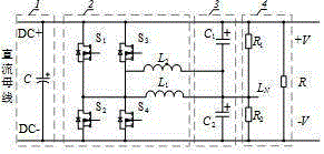
[0027] Such as figure 1 As shown, a voltage balancer based on an interleaved buck-boost circuit includes a DC link 1, a bidirectional interleaved buck-boost converter 2, an output filter circuit 3 and a load 4, and the bidirectional interleaved buck-boost converter 2 The positive terminal and the negative terminal are respectively connected to the positive potential link DC+ and the negative potential link DC- of the DC link 1, the common terminal of the bidirectional interleaved buck-boost converter 2 and the capacitor common terminal of the output filter circuit 3 The connection constitutes the neutral line and thus constitutes the distribution form of the bipolar busbar.

[0028] The DC link 1 includes a positive potential link DC+, a negative potential link DC- and a decoupling capacitor C , the decoupling capacitor C The anode and cathode are connected across DC+ and DC- respectively.

[0029] The bidirectional interleaved buck-boost converter 2 is composed of a first ...

Embodiment 2

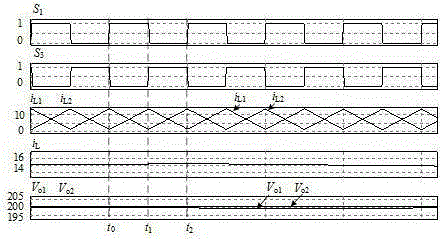
[0033] Combine below Figure 2-9 The specific working principle of this preferred embodiment is described: (the balancer based on the bidirectional interleaved buck-boost circuit adopts complementary PWM drive mode for interleaving control, the control signal of the first phase buck-boost circuit and the control signal of the second road buck-boost circuit The signals differ by 180o. Then the first switch tube S 1 and the third switching tube S 3 The drive signal difference of 180o, then the second switch tube S 2 and the fourth switching tube S 4 The difference between the drive signals is 180o; the first switch tube S 1 and the second switch tube S 2 The driving signals of the are complementary and have a certain dead zone, the third switch tube S 3 and the fourth switching tube S 4 The drive signals are complementary and have a certain dead zone. )

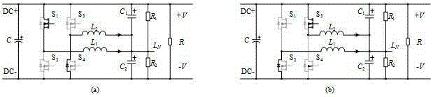
[0034] Such as figure 2 Shown, for this preferred embodiment load R 1 >R 2 , and the equivalent circuit diagram...


PUM


Abstract

The invention relates to an alternative-boost-buck-circuit-based voltage equalizer comprising a direct-current link, a bidirectional alternative boost-buck converter, an output filter circuit and a load. A positive terminal and a negative terminal of the bidirectional alternative boost-buck converter are respectively hooked to a positive potential link and a negative potential link of the direct-current link and a common terminal of the bidirectional alternative boost-buck converter and a capacitance common terminal of the output filter circuit are connected to form a neutral line, thereby forming a dual-polarity bus distribution mode. According to the voltage equalizer provided by the invention, with the alternative control technology, the power level can be increased conveniently and the current pulse of the direct-current link can be effectively reduced, thereby reducing the decoupling capacitance of the direct-current link. Meanwhile, currents flowing through the neutral point almost have no pulsation, so that the filter capacitance can be substantially reduced. The alternative-boost-buck-circuit-based voltage equalizer is suitable for a distribution system of a direct-current micrgrid as well as a bipolar bus distribution power supply system on a ship or a plane, especially for an aerospace direct-current distribution system with a strict size requirement.

Description

technical field [0001] The present invention relates to the field of power electronics application technology, control technology of power electronic converter and distributed power supply and distribution technology, in particular to a voltage balancer based on interleaved buck-boost circuit, which is used to construct the neutral line and solve the problem of positive and negative The problem of unbalanced polar load belongs to the technical field of DC / DC conversion. Background technique [0002] Microgrid is a form of power distribution that effectively utilizes distributed power sources. With the development of distributed power sources (such as solar cells, fuel cells, wind turbines, gas turbines, and biogas power generation, etc.), research on microgrid systems has attracted many academics. organization's attention. Compared with the AC microgrid, the DC microgrid is more convenient for the access of distributed power sources. Since there are no problems such as sync...

Claims


Application Information

Patent Timeline
Patent Type & Authority Applications(China)
IPC IPC(8): H02M3/156
Inventor 汪飞雷志方陈名胜梁东
Owner SHANGHAI UNIV
Why Eureka
Try Eureka