Wavelength selective switch employing an LCoS device and having reduced crosstalk

A wavelength, optical device technology, applied in the field of wavelength selective switches using LCoS devices and having reduced crosstalk, can solve the problems of unwanted optical crosstalk, unwanted energy coupling, etc.

Active Publication Date: 2016-01-06
莫仕有限责任公司
View PDF7 Cites 21 Cited by
  • Summary
  • Abstract
  • Description
  • Claims
  • Application Information

AI Technical Summary

Problems solved by technology

[0003] Although wavelength selective switches using LCoS devices have some very attractive performance characteristics, they also suffer from undesired optical crosstalk, which involves undesired coupling of energy from an input port to an output port at a specific wavelength

Method used


Image

  • Wavelength selective switch employing an LCoS device and having reduced crosstalk
  • Wavelength selective switch employing an LCoS device and having reduced crosstalk
  • Wavelength selective switch employing an LCoS device and having reduced crosstalk

Examples


Embodiment Construction

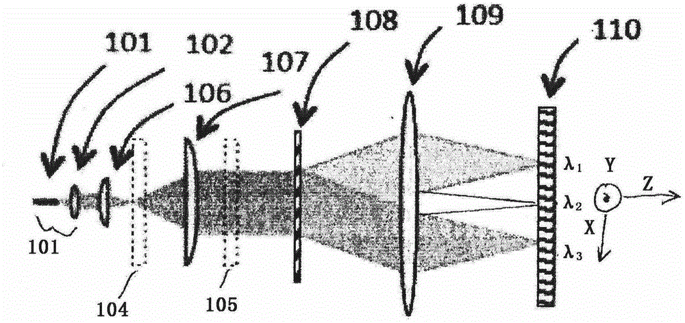
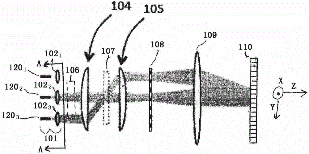
[0011] Figure 1A and Figure 1B Top and side views, respectively, of one example of a simplified optical device such as a free-space WSS 100 that may be used with embodiments of the present invention. Light is input and output to WSS 100 through optical waveguides such as optical fibers serving as input ports and output ports. Such as Figure 1B As best shown, fiber collimator array 101 may include a plurality of individual optical fibers 120 1 、120 2 and 120 3 , the multiple single fibers are respectively coupled to the collimator 102 1 、102 2 and 102 3 . Light from one or more optical fibers 120 is converted by collimator 102 into a free-space beam. The rays exiting the port array 101 are parallel to the z-axis. exist Figure 1B Although only three fiber / collimator pairs are shown for port array 101, more generally any suitable number of fiber / collimator pairs may be used.

[0012] A pair of telescopes or beam expanders amplifies the free-space beam from port arr...


PUM


Abstract

An optical device in which crosstalk due to scattering is reduced includes an optical port array having at least one optical input for receiving an optical beam and at least one optical output. The input and outputs extend along a common axis. A dispersion element receives the optical beam from the optical input and spatially separates the optical beam into a plurality of wavelength components. A focusing element focuses the plurality of wavelength components and a programmable optical phase modulator receives the focused plurality of wavelength components. The modulator is configured to steer the wavelength components to a selected one of the optical outputs. The programmable optical phase modulator is oriented with respect to the optical port array so that an axis along which the optical beam is steered is non-coincident with the common axis along which the input and outputs extend.

Description

Background technique [0001] Optical networks use wavelength selective switches (WSS) to dynamically route optical wavelength signals from source to destination. WSS devices typically rely on wavelength-manipulating elements such as liquid crystal on silicon (LCoS) devices or microelectromechanical (MEMS) mirror arrays to perform this transmission. [0002] LCoS devices include a liquid crystal material sandwiched between a transparent glass layer with transparent electrodes and a silicon substrate divided into a two-dimensional array of individually addressable pixels. Each pixel is individually driven by a voltage signal to provide a localized phase change to the optical signal, thereby providing a two-dimensional array of phase-manipulated regions. Once the optical signal has been spatially separated by a diffractive element, such as a diffraction grating, the individual spectral components can be manipulated. The spatial separation of spectral components is directed over ...

Claims


Application Information

Patent Timeline
Patent Type & Authority Applications(China)
IPC IPC(8): G02B26/08G02B6/26
CPCG01J2003/1213G02B6/356G02B26/0833
Inventor 杰斐逊·L·瓦格纳
Owner 莫仕有限责任公司
Why Eureka
Try Eureka