Multi-section implant assembly and manufacturing method thereof
A multi-stage implant technology, applied in the field of biomedical engineering, can solve the problems of poor osseointegration, poor mechanical structural properties, and easy loosening of implants, and achieve the effects of fast molding speed, short manufacturing cycle, and excellent mechanical structural properties
- Summary
- Abstract
- Description
- Claims
- Application Information
AI Technical Summary
Problems solved by technology
Method used
Image
Examples
specific Embodiment approach ( 1
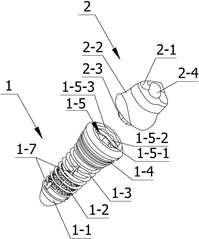
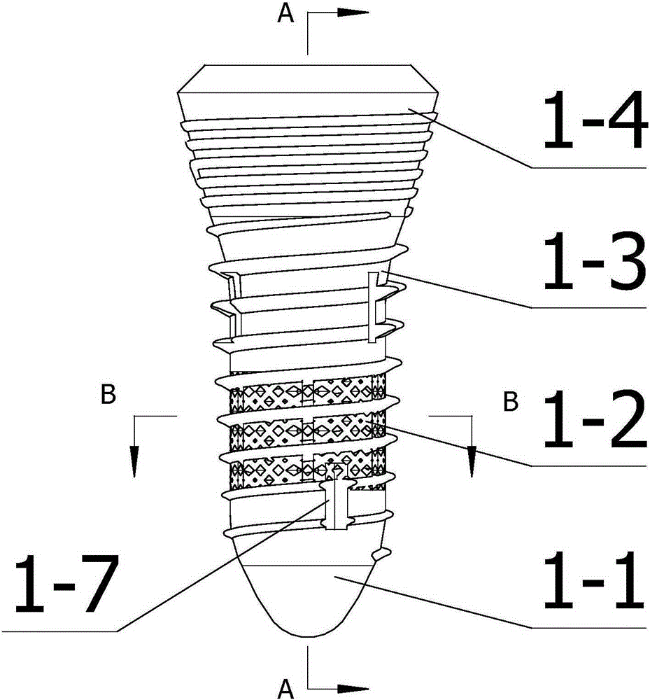
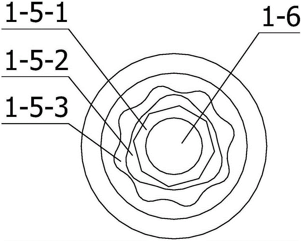
[0041] Such as Figure 1-7Shown is a multi-segment implant assembly provided by the present invention, including an implant 1, a personalized abutment 2 connected to the upper end of the implant 1, and fixing bolts connected between the implant 1 and the personalized abutment 2, The implant 1 includes implant segment one 1-1, implant segment two 1-2, implant segment three 1-3 and implant transgingival segment 1-4 arranged sequentially from bottom to top. Section 2 1-2 is a porous section. The implant body 1 is provided with a threaded counterbore 1-6, and the upper end of the implant 1 is provided with a personalized abutment located above the threaded counterbore 1-6 and extending inward. 2 connected abutment interface 1-5; the personalized abutment 2 includes a crown connection section 2-1, an abutment transgingival section 2-2 and an implant connection section 2-3 arranged from top to bottom. The implant connection section 2-3 is matched with the abutment interface 1-5, an...
specific Embodiment approach ( 2
[0050] A method for preparing a multi-segment implant component, characterized in that: the method includes sequentially performing 3D scanning, CAD modeling and 3D printing;
[0051] The 3D scanning is to use a 3D scanner to scan the patient's oral cavity and affected teeth to obtain the shape information of the implant 1 and the personalized abutment 2;
[0052] The CAD modeling is based on the data scanned by three-dimensional software, combined with the tooth position, shape and alveolar bone modulus of the patient's affected tooth to design the implant 1 and personalized abutment 2 that meet the requirements;
[0053] The 3D printing is to print the implant 1 and the personalized abutment 2 designed by CAD modeling with a 3D printer.
[0054] The design steps of the porous structure in the multi-segment implant assembly are as follows:
[0055] 1) Simulation stage
[0056] Through theoretical analysis, under the same force, the strain of bending deformation is greater t...
Embodiment 1
[0063] Such as Figure 8 As shown, a porous structure implant provided by the present invention includes an implant segment 1-1, an implant segment 2 1-2, an implant segment 3 1-3, and an implant segment arranged sequentially from bottom to top. The gingival segment 1-4, the implanted segment 1-2 is a porous segment, the Young's modulus of the outer surface of the porous segment is 10GPa, the Young's modulus of the center of the porous segment is 45GPa, and from the outer surface to the The central position realizes the gradient increase, and the implant body 1 is provided with threaded counterbores 1-6, and the upper end of the implant 1 is provided with a threaded counterbore 1-6 and extending inward for connecting with the personalized abutment 2. The abutment interface 1-5; the gingival piercing section 1-4 is an inverted truncated cone, the height of the inverted truncated cone is 3.75mm, the taper of the inverted truncated cone is 108 degrees, and the maximum diameter of...
PUM
| Property | Measurement | Unit |
|---|---|---|
| Young's modulus | aaaaa | aaaaa |
| Taper | aaaaa | aaaaa |
| Depth | aaaaa | aaaaa |
Abstract
Description
Claims
Application Information
 - R&D
- Intellectual Property
- Life Sciences
- Materials
- Tech Scout
- Unparalleled Data Quality
- Higher Quality Content
- 60% Fewer Hallucinations
Browse by: Latest US Patents, China's latest patents, Technical Efficacy Thesaurus, Application Domain, Technology Topic, Popular Technical Reports.
© 2025 PatSnap. All rights reserved.Legal|Privacy policy|Modern Slavery Act Transparency Statement|Sitemap|About US| Contact US: help@patsnap.com


