Quick blanking and drawing two-mode hydraulic machine and working method thereof

A hydraulic press and fast technology, applied in the field of hydraulic machinery, can solve the problems of high cost and price of mechanical presses, increased equipment occupied volume, insufficient hydraulic oil, etc., to reduce equipment investment costs, save space, and slide stably and smoothly. Effect

Active Publication Date: 2016-01-13
青岛三维汽车装备有限公司
View PDF5 Cites 2 Cited by
  • Summary
  • Abstract
  • Description
  • Claims
  • Application Information

AI Technical Summary

Problems solved by technology

[0003] The mechanical press is fast and efficient in the blanking process, but the mechanical press has a small stroke and a small opening. If it is used in the stretching process, the stretching speed is too fast, and the product is easy to tear. The mechanical press also has costs and prices. Higher disadvantages; while conventionally designed hydraulic presses have large openings and large strokes, soft stretching process, good quality of stretched products, and low manufacturing cost and price, but when using hydraulic presses for blanking process, the stroke is too large. The speed of the hydraulic machine is slow and the efficiency is low. When punching, the plunger rod first falls freely, injects oil through the air pressure, and then pumps the hydraulic oil. When punching, the hydraulic oil in the cylinder is not sufficient, the pressure is insufficient, and the punching effect is not ideal.
In order to stretch and punch the workpiece, it is necessary to purchase mechanical presses and hydraulic presses separately, which is extremely expensive and increases the volume occupied by the equipment

Method used


Image

  • Quick blanking and drawing two-mode hydraulic machine and working method thereof
  • Quick blanking and drawing two-mode hydraulic machine and working method thereof

Examples


Embodiment 1

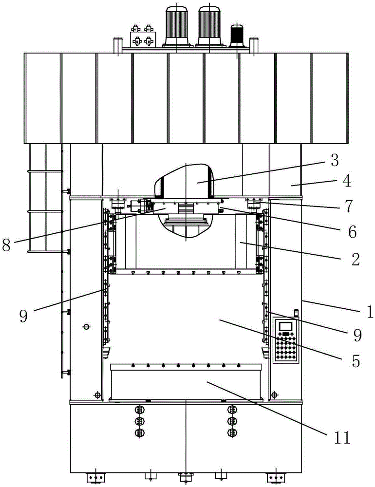
[0018] Such as figure 1 As shown, the rapid punching and stretching double-mode hydraulic press includes a frame 1 on which a sliding beam 2 and a pressurized oil cylinder 3 are installed.

[0019] The pressurized oil cylinder 3 is vertically and slidably installed on the upper beam 4 provided on the top of the frame 1, and the sliding beam 2 is slidably installed in the working chamber 5 provided in the middle of the frame 1. The plunger rod of the pressurized oil cylinder 3 and the sliding beam 2 connected.

[0020] Locking mechanism 6 is installed on the upper crossbeam 4, and the cylinder block of pressurized oil cylinder 3 is positioned at locking mechanism 6, and return stroke oil cylinder 7 is fixedly installed on the upper crossbeam 4, and the piston rod of return stroke oil cylinder 7 links to each other with sliding crossbeam 2.

[0021] During the initial state, the pressurized cylinder 3 and the sliding crossbeam 2 are all located at the top, and the piston rods a...

Embodiment 2

[0030] The structural composition of embodiment two is basically the same as that of embodiment one, the difference is that: locking mechanism 6 includes holding arm 8 and clamping driving device arranged left and right, and the inner wall of holding arm 8 is connected with the outer wall of cylinder by thread, and is held tightly. The arms 8 are all slidably installed on the upper beam 4, and the clamping drive device drives the clamping arms 8 to slide.

[0031] When it is necessary to position and lock the pressurized cylinder 3, the clamping drive device drives the two clasping arms 8 to close together, hugging the cylinder body of the pressurized cylinder 3, and the inner wall of the clasped arm 8 is threadedly engaged with the outer wall of the cylinder, through pressure and The threaded connection completes the fixing of the pressurized oil cylinder 3. The two locking methods work together to ensure a firm fixation.

[0032] The clamping driving device can be a power d...

Embodiment 3

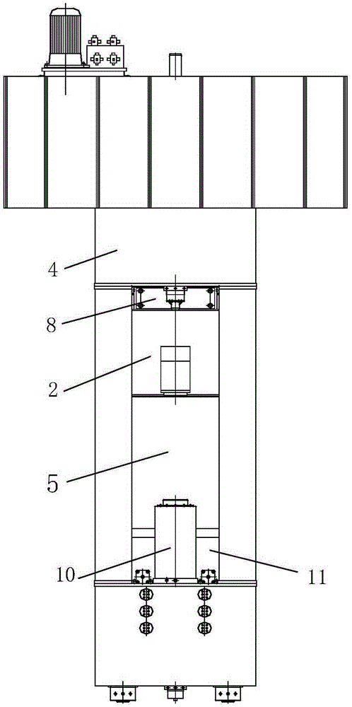
[0034] The structure composition of embodiment three is basically the same as that of embodiment one, the difference is: as figure 2 As shown, the two sides of the sliding beam 2 are correspondingly installed on the guide rails 9 vertically arranged on both sides of the working chamber 5 of the frame 1, and the buffer cylinder 10 is installed on the frame 1 corresponding to the lower end of the guide rail 9.

[0035] Sliding support on both sides of the sliding beam 2, and the lower part is blocked by the buffer cylinder 10 to ensure the stable operation of the sliding beam 2 and avoid excessive impact of the sliding beam 2 during fast punching, which will cause damage to the equipment.


PUM


Abstract

A quick blanking and drawing two-mode hydraulic machine comprises a rack. A sliding beam and a pressurization oil cylinder are installed on the rack. The pressurization oil cylinder is vertically installed on an upper beam in a sliding manner, wherein the upper beam is arranged at the top of the rack. The sliding beam is installed in a working cavity in a sliding manner, wherein the working cavity is arranged in the middle of the rack. A plunger rod of the pressurization oil cylinder is connected with the sliding beam. A locking mechanism is installed on the upper beam. A cylinder body of the pressurization oil cylinder is located in the locking mechanism. Stroke return oil cylinders are fixedly arranged on the upper beam. Piston rods of the stroke return oil cylinders are connected with the sliding beam. By the adoption of the quick blanking and drawing two-mode hydraulic machine, the blanking and drawing functions are achieved through hydraulic pressure, the dual purposes are achieved through one machine, equipment investment cost is reduced, and the space occupied by equipment can be saved as well. In the blanking process, the pressurization oil cylinder and the sliding beam fall synchronously, enough blanking inertia can be generated, oil is injected into the pressurization oil cylinder to apply force, and enough pressure can be output by the equipment in the blanking process; and in the oil injection and force applying processes of the pressurization oil cylinder, an oil cavity of the pressurization oil cylinder is basically free of air, the oil pressure in the oil cavity is large due to pumped hydraulic oil, pressure output in the blanking process is further guaranteed, and the blanking effect is guaranteed.

Description

technical field [0001] The invention relates to the field of hydraulic machinery, in particular to a fast punching and stretching double-mode hydraulic press and a working method thereof. Background technique [0002] At present, in the sheet metal production and processing enterprises at home and abroad, in the process of sheet metal processing, most of the rapid punching process is completed by mechanical presses, while the stretching process is completed by hydraulic presses. This is because the mechanical presses and hydraulic presses themselves There is an essential difference in structure and velocity characteristics. [0003] The mechanical press is fast and efficient in the blanking process, but the mechanical press has a small stroke and a small opening. If it is used in the stretching process, the stretching speed is too fast, and the product is easy to tear. The mechanical press also has costs and prices. Higher disadvantages; while conventionally designed hydrau...

Claims


Application Information

Patent Timeline
Patent Type & Authority Applications(China)
IPC IPC(8): B21D35/00B21D24/00B21D28/02B21D28/20
Inventor 金延红
Owner 青岛三维汽车装备有限公司
Why Eureka
Try Eureka