Lifting and positioning device for vacuum chamber optical components

A technology for optical components and lifting positioning, which is applied in the direction of optical components, optics, optical surface grinders, etc., can solve the problems of prolonging energy, waste, and large repeated positioning errors, and achieves the advantages of convenient use, simple overall structure, and small repeated positioning errors Effect

Active Publication Date: 2017-12-12
CHINA WEAPON SCI ACADEMY NINGBO BRANCH
View PDF6 Cites 0 Cited by
  • Summary
  • Abstract
  • Description
  • Claims
  • Application Information

AI Technical Summary

Problems solved by technology

[0006] ① To increase the trolley device for conveying workpieces, the wires that provide power for the motor need to move with the conveying trolley, and wire protection devices are required; there will be a passing space for the conveying trolley to enter the process vacuum chamber from the vacuum chamber of the transfer chamber, and the transfer window will be increased The geometric size will prolong the time for the vacuum system to meet the process requirements and cause energy waste
[0007] ②The structure of the four-linkage is complex, and the lifting distance is a constant value once the design is completed. It is not possible to choose a range according to the process requirements and different workpieces, which is relatively limited.
[0008] ③Poor positioning repeatability of optical components, large repeat positioning error

Method used


Image

  • Lifting and positioning device for vacuum chamber optical components
  • Lifting and positioning device for vacuum chamber optical components
  • Lifting and positioning device for vacuum chamber optical components

Examples


Embodiment Construction

[0031] The present invention will be further described in detail below in conjunction with the accompanying drawings and embodiments.

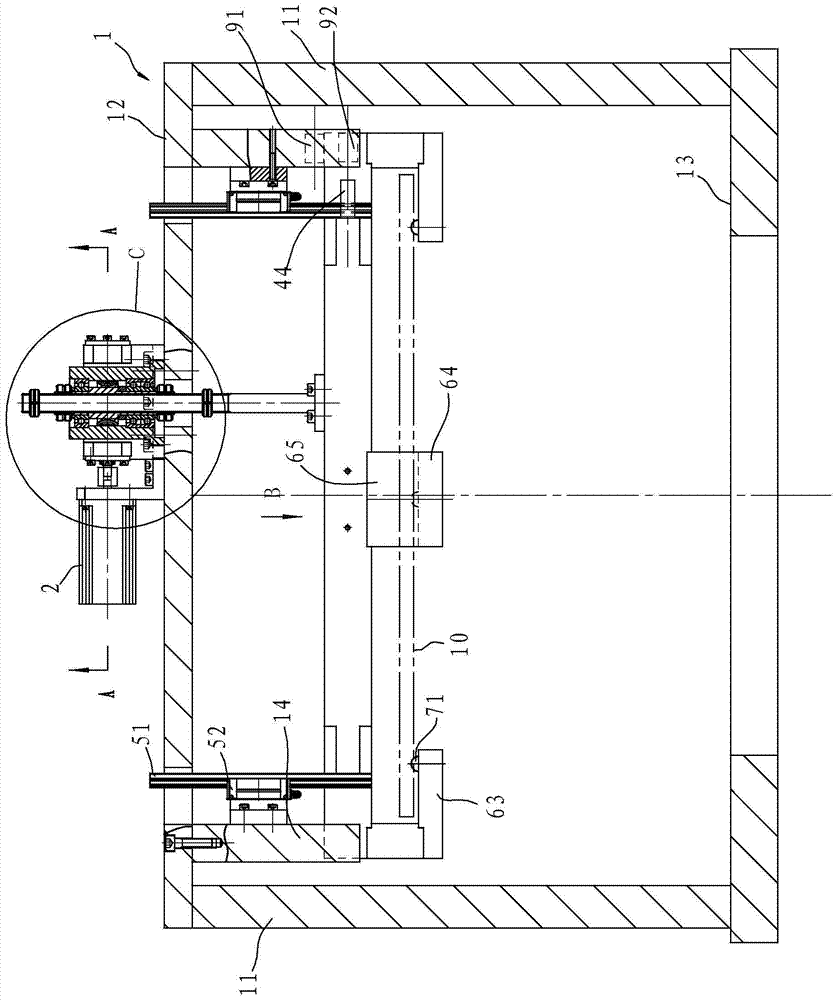
[0032] Such as figure 1 As shown, the vacuum chamber optical element lifting and positioning device in this embodiment includes a frame body 1, a motor 2, a tray 4, a screw rod 3 and a guide mechanism 5, and the frame body 1 includes two vertical plates 11 and is located on the vertical plate 11. Top plate 12, top plate 12 offers the through hole that passes for screw mandrel 3, and top plate 12 lower end face is extended downwards and is provided with connecting plate 14, and for improving fastness, vertical plate 11 bottoms are connected and fixed with base plate.

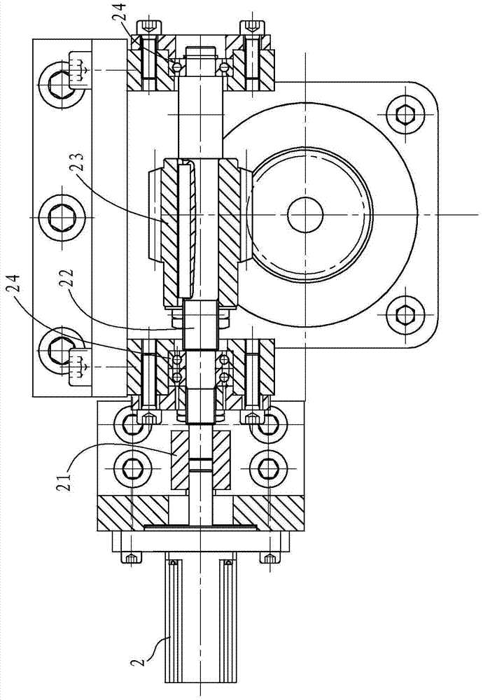
[0033] combine image 3 As shown, the motor 2 is arranged on the top plate 12, and the output end of the motor 2 is provided with a coupling 21, and the coupling 21 is connected with a rotating shaft 22, and the rotating shaft 22 is provided with a synchronously rotating worm sc...


PUM


Abstract

A vacuum chamber optical element lifting and positioning device is characterized in that the vacuum chamber optical element lifting and positioning device comprises a frame body, a motor, a tray, a lead screw and a guide mechanism; the frame body comprises at least two stand plates and a top plate arranged on the stand plates; the power output end of the motor is connected with a worm; the tray comprises at least two longitudinal beams and a beam arranged between the longitudinal beams; each longitudinal beam is provided with a first positioning ball with the upward end face; the beam is provided with a second positioning ball with the upward end face as well; in addition, the two first positioning balls and the second positioning ball are not located on a straight line and can repeatedly position optical elements; the lead screw is vertically arranged on the beam of the tray; a rotating nut in rotation fit with the lead screw is arranged at the upper end of the lead screw; and worm teeth in rotation fit with the worm are arranged on the outer wall of the rotating nut. Compared with the prior art, the vacuum chamber optical element lifting and positioning device has the beneficial effects that the overall structure is simple, use is convenient, control is accurate, and the lifting distance can be easily regulated; and an accurate three-point positioning mechanism is arranged so that the repeated positioning error can be small.

Description

technical field [0001] The invention relates to a lifting and positioning device, which is applied to the ion beam trimming and polishing process of aspherical optical lenses in a vacuum environment. Background technique [0002] With the rapid development of science and technology, strong laser optical systems and high-definition optical systems, such as tactical laser weapon optical systems, long-distance ultraviolet and infrared imaging detection systems, deep space photoelectric detection systems, lightweight image stabilization and sighting systems, laser For radar systems, deep ultraviolet and extreme ultraviolet lithography systems, etc., the demand for optical components with sub-nanometer surface roughness and nanometer surface precision is increasingly urgent, and ultra-precision optical components and their manufacturing technologies are needed to achieve. The requirements for the development of advanced optoelectronic systems are increasing, and the precision and...

Claims


Application Information

Patent Timeline
Patent Type & Authority Patents(China)
IPC IPC(8): B24B13/00B24B13/005B24B41/02
CPCB24B13/00B24B13/0031B24B13/0055B24B41/02
Inventor 王大森聂凤明吴庆堂张广平郭成君裴宁纪淑花朱鸿磊
Owner CHINA WEAPON SCI ACADEMY NINGBO BRANCH
Why Eureka
Try Eureka