
Nursing robot and motion control system

A motion control system and robot technology, applied in the field of robotics, can solve problems such as incomparability of functions, lack of autonomous movement, and single function.

Inactive Publication Date: 2016-01-13
BEIHANG UNIV
View PDF3 Cites 26 Cited by
  • Summary
  • Abstract
  • Description
  • Claims
  • Application Information

AI Technical Summary

Problems solved by technology

[0003] The structure of the existing nursing robot-related patent products is too simple, the functions are simplified and single, the control system is unclear, and the implementability is not strong
After searching the existing technology, it was found that the invention patent "household service robot" with the application number CN201210418615.7 includes a torso, a head and limbs, each part is detachable, and the head includes an expression display device, which can be used according to The control signal shows facial expressions, but the application scene is simple, and the function of life assistance cannot be realized; the invention patent "nursing robot" with the application number CN201110239654.6 adopts a split double-layer bed surface structure, and is an intelligent walking tool that can meet The requirements for diverse body positions and intelligent toilet sitting in nursing care are not of the same type as the indoor mobile robot involved in this patent. Although the names are the same, they are not comparable in function; the invention patent with the application number CN201410706366. Type escort robot and system", including the pet shell and the sensor components installed inside the pet shell, the main controller and the execution components, but obviously, the function of this robot is relatively simple, and it does not have the ability to move autonomously and assist in the completion of picking and opening the door. and other functions

Method used


Image

  • Nursing robot and motion control system
  • Nursing robot and motion control system
  • Nursing robot and motion control system

Examples


Embodiment Construction

[0035] The present invention will be described in detail below in conjunction with the accompanying drawings and embodiments.

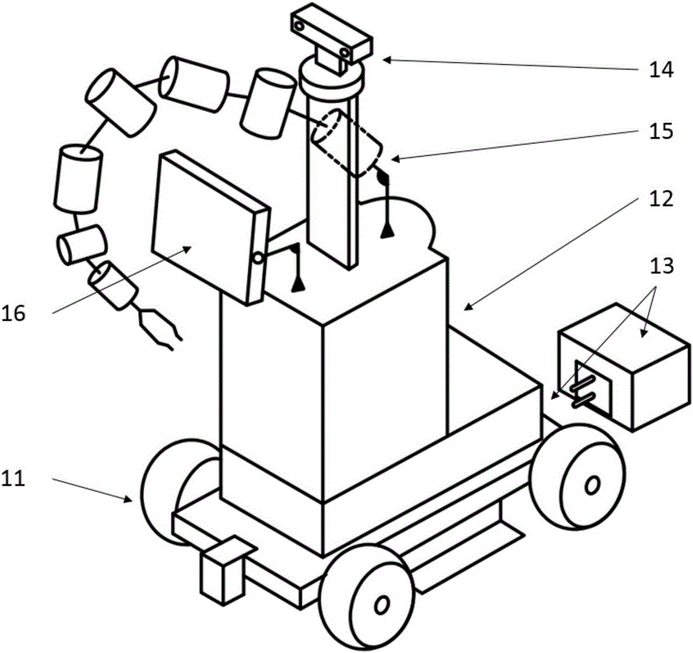
[0036] The present invention is a kind of nursing robot and motion control system, comprise hardware platform 1 and motion control system 2; The nursing robot has omnidirectional flexible movement, autonomous obstacle avoidance, autonomous charging and other functions.

[0037] The hardware platform 1 includes an omnidirectional mobile chassis 11, a trunk skeleton structure 12, an autonomous charging module 13, a binocular vision module 14, a mechanical arm module 15, and a display module 16, such as figure 1 shown.

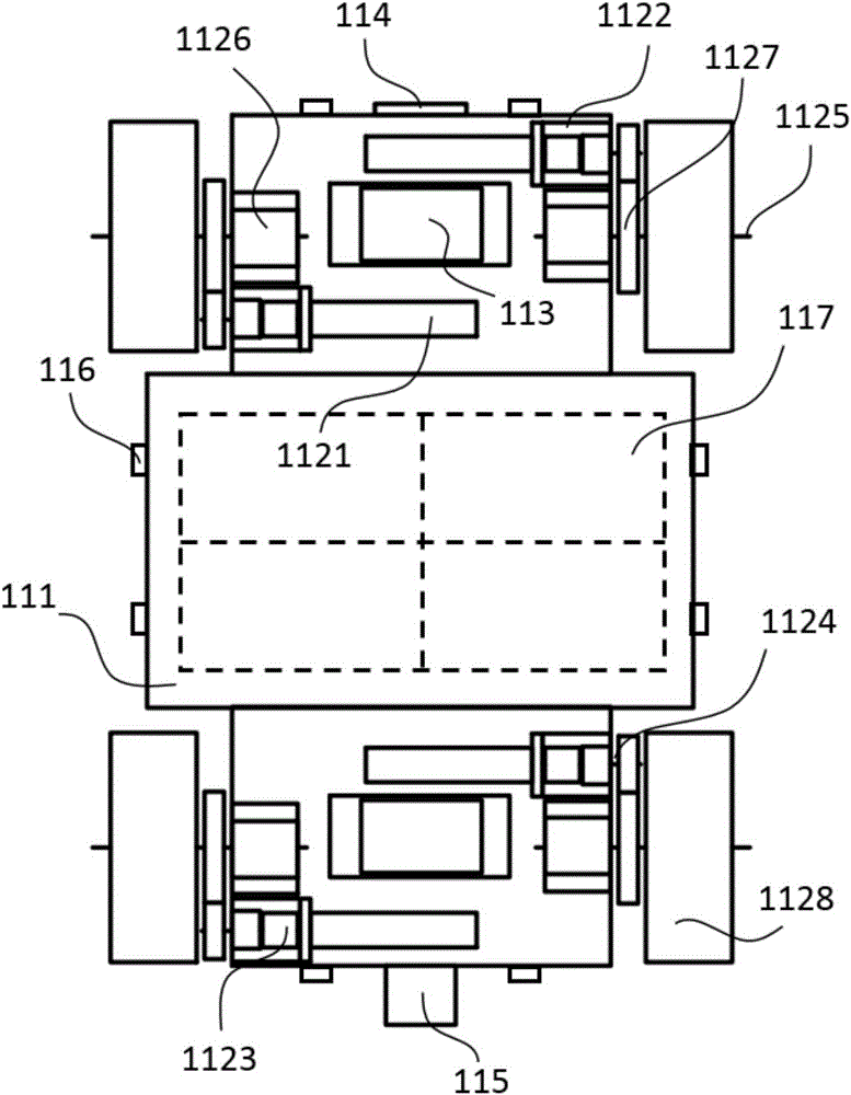
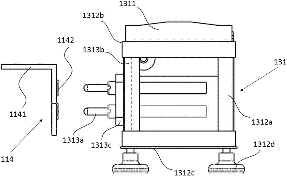
[0038] The omnidirectional mobile chassis 11 includes a chassis structure 111, a motor and an omnidirectional wheel module 112, a driver module 113, a vehicle charging module 114, a laser radar module 115, an ultrasonic sensor module 116 and a mobile power supply module 117, such as figure 2 shown and Figure 5 shown.

[0039] The c...


PUM

PropertyMeasurementUnit
Corneraaaaaaaaaa

Abstract

The invention discloses a nursing robot and a motion control system. The nursing robot comprises a hardware platform and the motion control system. The hardware platform comprises an omni-directional moving chassis, a body skeleton structure, an autonomous charging module, a binocular vision module, a mechanical arm module and a display screen module. According to the motion control system, a generalized matrix is used for conducting positive and athwart kinematics analysis on the moving chassis with four Mecanum wheels being distributed in a rectangular mode, and closed-loop control and feedback of the center speed of the chassis are achieved; obstacle avoidance control over the chassis is achieved based on ultrasonic sensors in the four directions of the chassis and a speed value linear mapping set threshold value. The motion control system achieves the functions of flexible omni-directional movement, autonomous obstacle avoidance, autonomous charging and the like of the nursing robot. The nursing robot is an intelligent indoor moving robot, and the diversified demands for life assisting of the old are met.

Description

technical field [0001] The invention relates to the technical field of robots, specifically, an intelligent nursing robot with functions such as autonomous movement, environment perception, fetching and opening doors, and human-computer interaction. Background technique [0002] The growth rate of the proportion of the elderly population in my country is accelerating and will continue until 2050; among them, the elderly disabled account for 53.2% of all disabled people, and the number of elderly people with mobility problems due to various disabilities is quite alarming; at the same time, the empty-nest elderly The proportion is increasing year by year. A considerable number of elderly people do not live with their children, nor do they have hired staff to take care of them. There is a serious shortage of professional nursing staff, and the cost of nursing care is also increasing. Most families lack professional family medical information services, and it is very difficult ...

Claims


Application Information

Patent Timeline
IPC IPC(8): B25J11/00B25J13/00
Inventor 陈殿生罗玄海张本光
Owner BEIHANG UNIV
Learn More