Composite material power transformation framework
A technology of composite material and substation frame, applied in buildings, towers, building types, etc., can solve problems such as poor stability, achieve high production efficiency, overcome insufficient hoop strength and rigidity, and reduce maintenance
- Summary
- Abstract
- Description
- Claims
- Application Information
AI Technical Summary
Problems solved by technology
Method used
Image
Examples
Embodiment 1
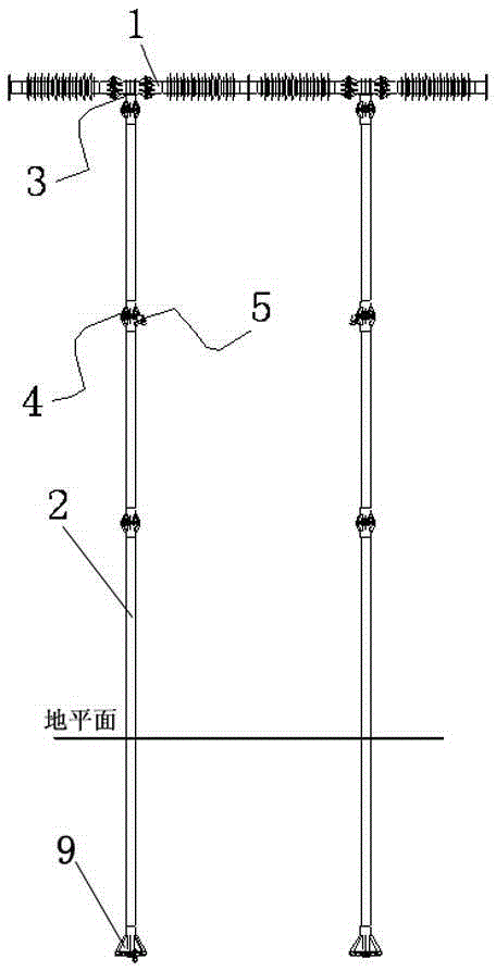
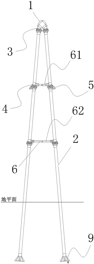
[0037] The present invention is a composite material substation structure, comprising a supporting column 2 and an insulating beam 1 arranged on the supporting column 2, the supporting column 2 is used to support the insulating beam 1, the supporting column 2 includes a composite material circular tube, and the insulating beam 1 It includes a composite material round rod prepared by a pultrusion process, and an insulating shed is crimped on the outer wall of the composite material round rod; the composite material round tube includes a base layer, a strengthening layer, a buffer layer and an outer layer arranged in sequence from the inside to the outside , the ratio of the thickness of the base layer, strengthening layer, buffer layer and outer layer to the outer diameter of the circular tube is 0.5~0.6:0.1~0.2:0.1~0.2:0.1~0.2:15; the base layer is specifically: Mg, 4~6%; Cr, 0.1~0.2%; Mn, 2.5~3.0%, V, 2.0~2.5%, Ti, 5.0~5.5%, and the balance is Al; the strengthening layer is sp...
Embodiment 2
[0039] According to the composite material transformation frame described in Embodiment 1, the support columns 2 are two groups of single rods, each group of single rods includes at least two stages of composite material circular tubes prepared by braiding, winding and pultrusion technology, and the composite material circular tubes of each stage are The pipes are connected by flange 4.
[0040] figure 1 It is a schematic diagram of a single-rod support structure of the present invention; the support column 2 in the figure is two groups of single rods, and each group of single rods includes three-stage composite material round pipes prepared by braiding, winding and pultrusion technology, and the composite material round pipes at all levels adopt the method of Lan 4 is connected.
Embodiment 3
[0042] According to the composite material substation structure described in Embodiment 1, the support columns 2 are in four groups, each of which is a herringbone support column 2, and each herringbone support column 2 includes at least one level of cross braces 6 and four levels of support columns. Composite material round tubes prepared by braiding, winding and pultrusion process, the composite material round tubes at all levels are connected by flange 4, and the flange 4 on the side (inner side) close to the insulating beam 1 is provided with a fixing hole for fixing the cross brace 6 .
[0043] figure 2 It is a schematic diagram of a herringbone support structure of the present invention; the support columns 2 of the herringbone support structure are four groups, and every two groups are a herringbone support column 2, and each herringbone support column 2 includes two-stage cross braces 6 and six-stage adopting Composite material round tubes prepared by braiding, windi...
PUM
| Property | Measurement | Unit |
|---|---|---|
| Density | aaaaa | aaaaa |
| Surface resistivity | aaaaa | aaaaa |
Abstract
Description
Claims
Application Information
 - R&D
- Intellectual Property
- Life Sciences
- Materials
- Tech Scout
- Unparalleled Data Quality
- Higher Quality Content
- 60% Fewer Hallucinations
Browse by: Latest US Patents, China's latest patents, Technical Efficacy Thesaurus, Application Domain, Technology Topic, Popular Technical Reports.
© 2025 PatSnap. All rights reserved.Legal|Privacy policy|Modern Slavery Act Transparency Statement|Sitemap|About US| Contact US: help@patsnap.com


