an exhaust gas burner

A technology of waste gas combustion and waste gas, which is applied in the direction of combustion method, combustion type, lighting and heating equipment, etc., can solve the problems of complex manufacturing process, poor combustion effect, scattered structure, etc., achieve simple structure, reduce overall cost, and uniform temperature distribution Effect

Active Publication Date: 2017-06-13
LUOYANG MINGYUAN PETROCHEM IND TECH +1
View PDF10 Cites 0 Cited by
  • Summary
  • Abstract
  • Description
  • Claims
  • Application Information

AI Technical Summary

Problems solved by technology

[0003] The purpose of the present invention is to overcome the defects existing in the existing CO incinerator and propose a waste gas burner. The technical problem to be solved is to make it have a high degree of integration, a compact and reliable structure, sufficient incineration, high thermal efficiency, easy operation, and effective Solve the defects of existing equipment such as complex manufacturing process, scattered structure, difficult operation, poor combustion effect, etc., so that it is more suitable for practical use

Method used


Image

  • an exhaust gas burner
  • an exhaust gas burner
  • an exhaust gas burner

Examples


Embodiment Construction

[0047] The present invention is further described in conjunction with accompanying drawing:

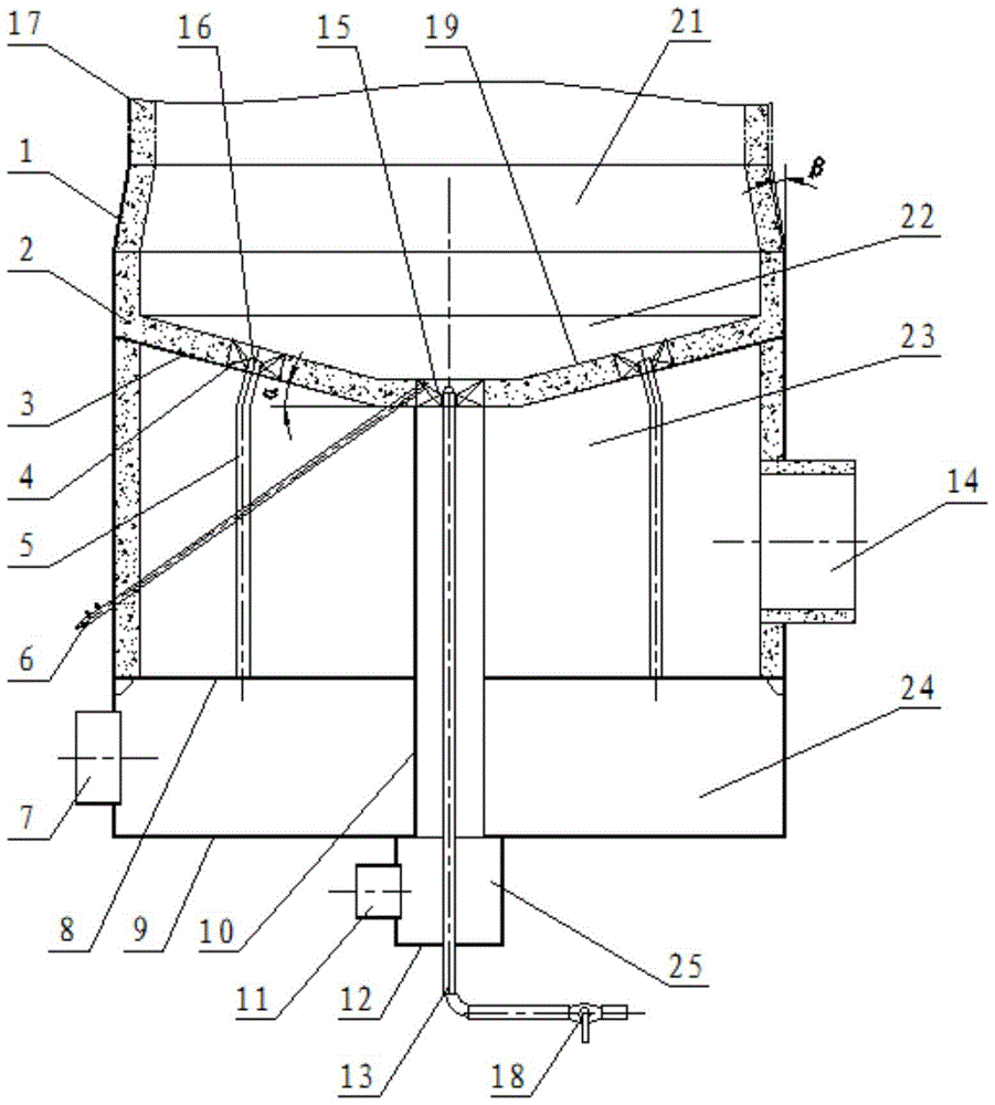
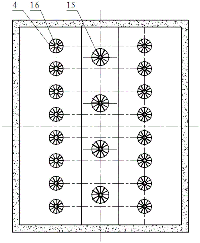
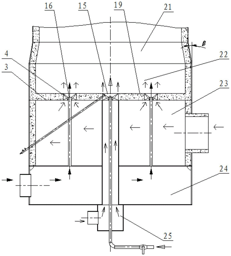
[0048] see Figure 1a , Figure 2a , Figure 3a , Figure 4a and Figure 5a , a waste gas burner, which is arranged at the lower part (or head) of the incinerator. All are provided with an independent ignition gun 6; from top to bottom, there are successively provided with an outlet contraction section 21, a combustion chamber 22, a distribution mixing plate 3, an exhaust gas collection cabin 23, an exhaust gas partition 8, a mixing air collection cabin 24, a mixing Air partition 9, combustion-supporting air assembly cabin 25; combustor combustion-supporting air outlet 15, exhaust gas outlet 4, and mixing air outlet 16 are reasonably distributed on the distribution mixing plate 3; each burner nozzle is provided with an independent fuel pipeline riser 13 And the valve 18; the burner is connected with the incinerator body 17 through the outlet contraction section 21.

[0049] In the ...


PUM


Abstract

An exhaust gas burner, which is installed at the lower part or the head of the incinerator, and a plurality of burner nozzles are arranged inside, and each burner nozzle is equipped with an independent ignition gun, a fuel pipeline rising pipe and a valve. To the bottom, there are outlet contraction section, combustion chamber, waste gas collection cabin, mixing air collection cabin, and combustion air collection cabin; the exhaust gas burner is connected with the incinerator body through the exit contraction section, and the waste gas collection cabin, The mixing air collection cabin and the combustion-supporting air collection cabin are all equipped with independent inlets, and each collection cabin is connected to the corresponding outlet on the distribution mixing plate through the corresponding riser pipe to form independent exhaust flow channels, mixing air flow channels, Combustion-supporting air flow channel; the fuel pipeline rising pipe of each burner burner is coaxially arranged with the combustion-supporting air rising pipe, and the outlet is arranged at the combustion-supporting air outlet. The exhaust gas burner proposed by the invention has high integration degree, compact and reliable structure, sufficient incineration, high thermal efficiency and convenient operation.

Description

technical field [0001] The invention belongs to burner technology and is suitable for waste gas incineration in industries such as oil refining, chemical industry, medicine and power plant, and specifically relates to a waste gas burner. Background technique [0002] In the refining and chemical industry, a large amount of toxic and harmful waste gas or waste gas with a certain calorific value is discharged during the production process. From the perspective of environmental protection and energy saving, it is not allowed to vent directly, and it needs to be treated by an incinerator before being discharged. In particular, during the operation of catalytic cracking units in refineries, incomplete catalyst regeneration and aerobic combustion produce a large amount of flue gas containing about 3-10% (V) CO and a small amount of combustible gas. This part of flue gas not only has a certain temperature (about 600 ° C) ), and contains a certain amount of CO gas that can be furthe...

Claims


Application Information

Patent Timeline
Patent Type & Authority Patents(China)
IPC IPC(8): F23G7/06
Inventor 程向锋
Owner LUOYANG MINGYUAN PETROCHEM IND TECH
Why Eureka
Try Eureka