
A concentrating field control system of a photothermal power station and its implementation method

A photothermal power station and field control technology, applied in solar heating systems, solar collector controllers, solar thermal power generation, etc. Problems such as the overall network system are not formed, and the effects of easy installation and maintenance, improved reliability and real-time performance, and improved equipment tolerance

Active Publication Date: 2018-03-13
DONGFANG BOILER GROUP OF DONGFANG ELECTRIC CORP
View PDF8 Cites 0 Cited by
  • Summary
  • Abstract
  • Description
  • Claims
  • Application Information

AI Technical Summary

Problems solved by technology

[0005] 1. The existing concentrating field control system of photothermal power plants is usually aimed at the mirror field. Since the mirror field and the heat sink are closely related, separating the mirror field and heat sink control systems has a greater safety risk;
[0006] 2. The existing concentrating field control system of photothermal power plants has not formed an overall network system. For example, the initial parameter detection and long-term operation correction of heliostats are independent of the control network, with low automation and low detection efficiency;
[0007] 3. The control devices used in the existing control system, such as large-scale use of PLC and DCS controllers, are expensive and waste resources;
[0008] 4. The sensors used in the existing control system, such as large-scale use of encoders, magnetic strip sensors, etc., are expensive, have a short life, are difficult to install and maintain, and have poor environmental tolerance;
[0009] 5. Most of the existing control systems use centralized control schemes, and the computing load of the upper computer in the concentrating field is heavy;
[0010] 6. The number of network structure layers in the existing control system is small, which is not conducive to the establishment of a large-scale concentrating field control network

Method used


Image

  • A concentrating field control system of a photothermal power station and its implementation method

Examples


Embodiment Construction

[0034] Specific embodiments of the present invention will be described in detail below in conjunction with the accompanying drawings.

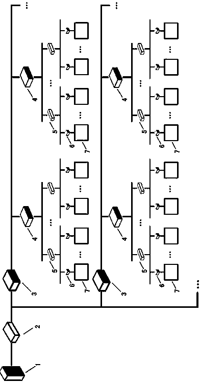
[0035] With the technological development of photothermal power generation systems and the increase of power station capacity, the scale of condensers in the concentrating field gradually expands, and the number of concentrating mirrors in a concentrating mirror field can reach tens of thousands or even hundreds of thousands. In the power station, 10,347 condenser mirrors are used. In the Ivan Pata power station in the United States, the number of condenser mirrors is as high as 175,000. For each condenser, it has independent motion trajectories and parameters at different times, and requires a "brain" to control; at the same time, the communication data of each condenser is about dozens of bytes, and the amount of communication data is small. It is uploaded to the host computer of the condenser field at all times, which results in a large num...


PUM


Abstract

The invention relates to the technical field of concentrator field control in a photothermal power station and discloses a concentrator field control system of a photothermal power station. The system particularly comprises a plurality of collecting mirrors and collecting mirror controllers corresponding to the collecting mirrors. The collecting mirror controllers are connected with rotary shaft control motors of the collecting mirrors. Multiple collecting mirrors form a cluster. Each cluster is provided with a cluster controller. Multiple collecting mirror clusters form a group. Each group is provided with a group controller. Multiple collecting mirror groups form an island. Each island is provided with an island controller. A concentrator field upper computer is connected with the island controllers. Public information of each layer is calculated through a corresponding layer controller, and data of the layer are packaged and compressed and upwards collected to the collecting mirror upper computer layer by layer. Through establishment of the control system, the calculation pressure of the upper computer is reduced, and the instantaneity and reliability of communication are remarkably improved. The invention further discloses an implementation method for concentrator field control over the photothermal power station.

Description

technical field [0001] The present invention relates to the technical field of photothermal power plant control, in particular to a control system for a concentrated field of a photothermal power station and an implementation method thereof. Background technique [0002] With the depletion of coal, oil, natural gas and other energy sources, the market demand for clean energy continues to increase, and solar thermal power generation has attracted more and more attention. At present, solar thermal power generation is mainly divided into tower type, trough type and Fresnel type. The basic principle of its power generation is to use a concentrating field composed of a large-scale array of plane mirrors, parabolic mirrors, or dish mirrors to collect solar heat energy, provide steam through a heat exchange device, and use a steam turbine to drive a generator to generate electricity. [0003] The concentrating field is the energy collection end of the photothermal power station, a...

Claims


Application Information

Patent Timeline
Patent Type & Authority Patents(China)
IPC IPC(8): F24S50/00F24S50/20
CPCY02E10/47
Inventor 何杰奚正稳华文瀚孙登科
Owner DONGFANG BOILER GROUP OF DONGFANG ELECTRIC CORP
Learn More