Magnet used for high-frequency welding device, high-frequency welding device and automatic peeling welding machine

A high-frequency welding and welding machine technology, applied in high-frequency current welding equipment, welding equipment, connections, etc., can solve problems such as high-frequency welding devices that cannot be applied to automation

Active Publication Date: 2016-01-20
东莞市镭邦光电科技有限公司
View PDF11 Cites 7 Cited by
  • Summary
  • Abstract
  • Description
  • Claims
  • Application Information

AI Technical Summary

Problems solved by technology

Not suitable for use in automated high-frequency welding devices

Method used


Image

  • Magnet used for high-frequency welding device, high-frequency welding device and automatic peeling welding machine
  • Magnet used for high-frequency welding device, high-frequency welding device and automatic peeling welding machine
  • Magnet used for high-frequency welding device, high-frequency welding device and automatic peeling welding machine

Examples


Embodiment Construction

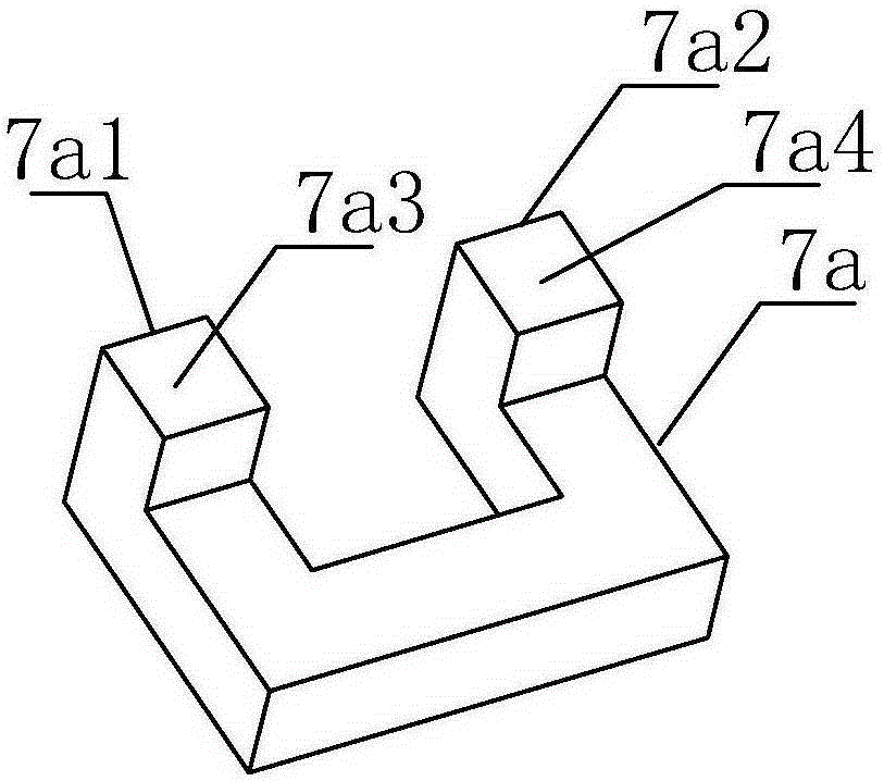
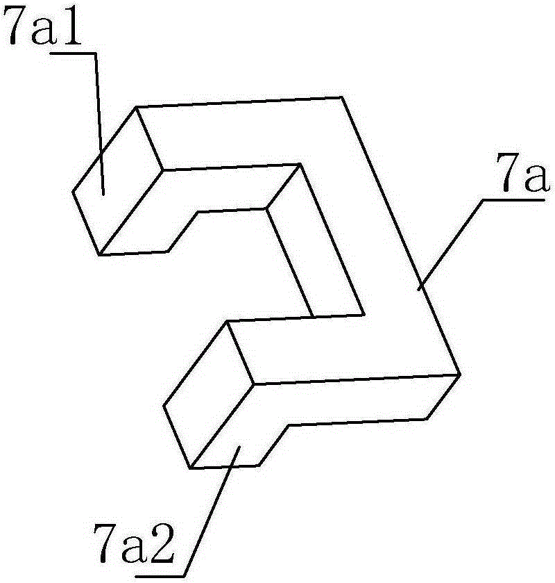
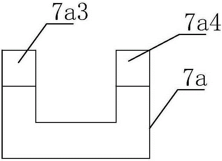
[0067] Such as Figure 1 to Figure 6 As shown, a magnet for a high-frequency welding device according to the present invention has a U-shaped magnet 7a, and bosses 46a and 46a are symmetrically extended on the same side of both ends.

[0068] The bosses 7a1, 7a2 have extended and diverted end faces 7a3, 7a4.

[0069] The end faces 7a3, 7a4 are attached and connected with upper and lower magnetic welding heads 7b, 7c which can move up and down relative to each other. The sides of the upper and lower magnetic welding heads 7b, 7c are in contact with the end faces 7a3, 7a4, and the upper and lower relative ends form a contact welding gap.

[0070] Such as Figure 34 to Figure 38 As shown, a high-frequency welding device includes a horizontal guide rail 1ab for guiding wire ends and a welding device 7 arranged on the opposite side of the horizontal guide rail 1ab. The welding device 7 includes a magnet 7a, an upper and lower magnet welding head 7b , 7c, welding head driving cyli...


PUM


Abstract

The invention provides a magnet used for a high-frequency welding device, the high-frequency welding device and an automatic peeling welding machine. The automatic peeling welding machine comprises a fixed cable clamp device, an initial cable cutting device, a locating movable cable clamp device, a peeling and cable trimming device, a forking and cable cutting device, the welding device and a cable supporting frame. The locating movable cable clamp device is arranged on one side of the fixed cable clamp device, and the initial cable cutting device, the forking and cable cutting device, the peeling and cable trimming device, a stamping block with an inverted-V-shaped opening and the welding device are arranged on the other side of the fixed cable clamp device in sequence. The cable supporting support is arranged outside the cable clamp fixing device. The magnet is in the U shape, and bosses are extended from the same sides of the two ends of the magnet symmetrically. The automatic peeling welding machine is high in automation level, high in production efficiency and low in equipment cost, and the technical effect that the production efficiency and the product quality are high is achieved. The high-frequency welding device used in the automatic peeling welding machine and the specially-used magnet for the high-frequency welding device are provided at the same time.

Description

technical field [0001] The invention relates to a wire stripping device for a non-metallic outer layer of a wire stripping body and a high-frequency welding device for realizing automatic welding after stripping, in particular to a magnet for a high-frequency welding device, a high-frequency welding device and an automatic peeling welding machine. Background technique [0002] When producing connecting lines such as HDMI, DVI, USB, SATA, DISPLAYPORT, etc., it is necessary to peel off the non-metallic outer layer of the connecting end of each branch body, cut flat, connect with the plug and weld after docking. The above processes are respectively passed The manual operation is completed step by step. To complete the above process, it is first necessary to arrange the wires one by one into multiple wire arranging fixtures, and then realize it on different working platforms. Due to the limitation of manual operation, it is easy to cause operational deviation and affect the stri...

Claims


Application Information

Patent Timeline
Patent Type & Authority Applications(China)
IPC IPC(8): B23K13/01H01R43/28
CPCB23K13/01B23K2101/38H01R43/28
Inventor 钟予锋冯金勇
Owner 东莞市镭邦光电科技有限公司
Why Eureka
Try Eureka