Counterweight-variable and hydraulic power-controllable automatic fixed shaft turning plate gate

A hydraulic automatic and flap gate technology, applied in the field of gates, can solve the problems of small gate opening, troublesome management, inflexible gate opening, etc., and achieve the effect of reducing the flow area

Active Publication Date: 2016-01-20
谢太生
View PDF6 Cites 7 Cited by
  • Summary
  • Abstract
  • Description
  • Claims
  • Application Information

AI Technical Summary

Problems solved by technology

Among them (1) the shaft of the vertical shaft revolving gate and the horizontal revolving gate cannot be fully automatically controlled. Once opened, the water volume is basically discharged, and the gate cannot automatically return to its position and close. It needs to be closed manually, and the upstream water level cannot be controlled artificially, which makes management troublesome; (2) non-continuous There are three types of gates, the hinged flap gate, the curved continuous hinged flap gate and the involute gate, which are complex in design and construction, and some gates have a small opening degree, which is unfavorable to the flood discharge of the project.
In addition, when the sluice is running, it will be blocked by a large number of floating objects, which will easily get stuck on the running track, resulting in inf

Method used


Image

  • Counterweight-variable and hydraulic power-controllable automatic fixed shaft turning plate gate
  • Counterweight-variable and hydraulic power-controllable automatic fixed shaft turning plate gate
  • Counterweight-variable and hydraulic power-controllable automatic fixed shaft turning plate gate

Examples


Embodiment Construction

[0031] The present invention will be further elaborated below in conjunction with embodiment.

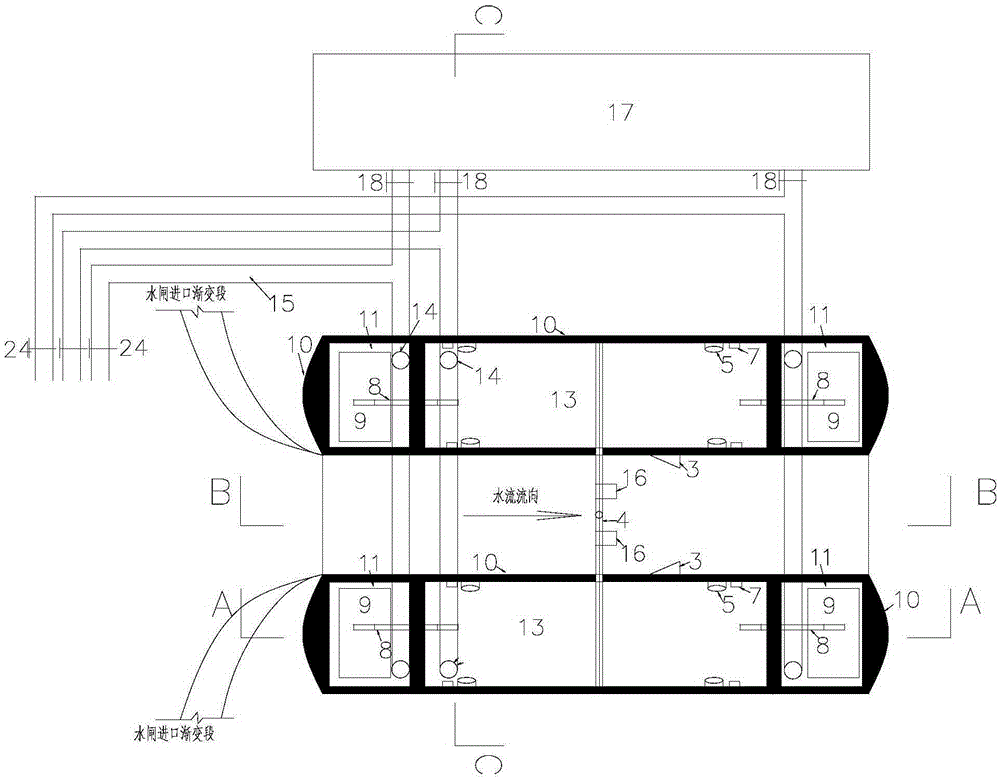
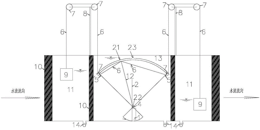
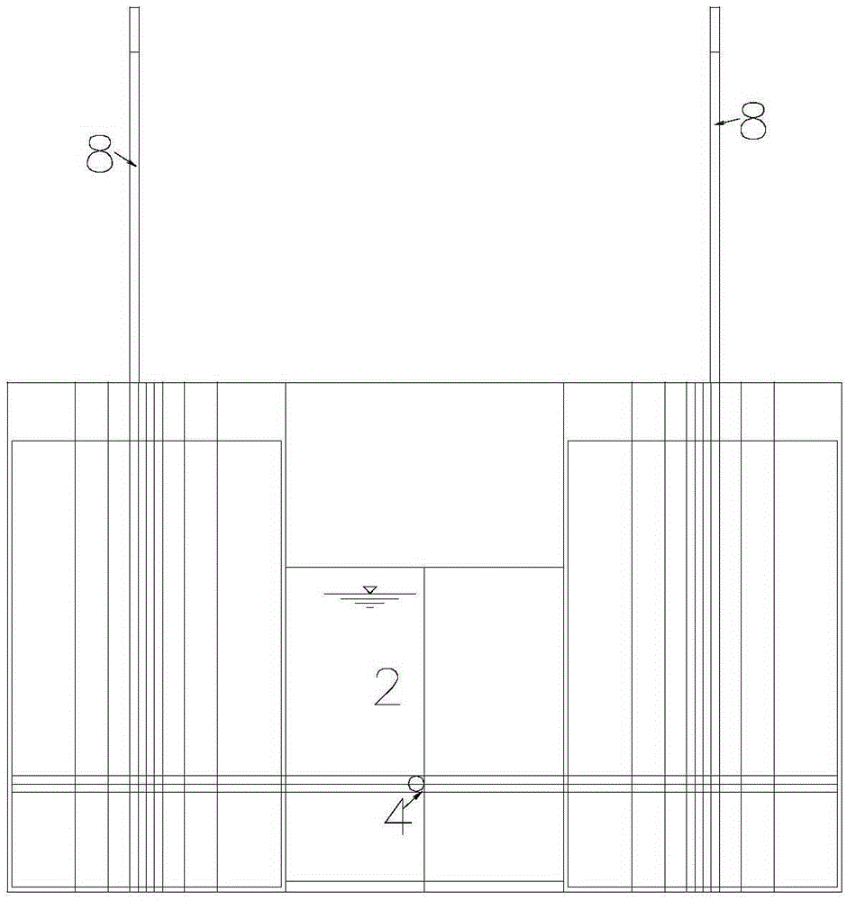
[0032] Such as Figure 1 to Figure 9 As shown, variable counterweight controllable hydraulic automatic fixed axis flap gate, the bottom of the gate 2 is fixed on the rotating shaft 4, the bottom of the backwater surface of the gate 2 is provided with a water tank 1, and the water tank 1 is provided on the side adjacent to the bottom of the gate 2 There is a water hole 19, and a vent hole 20 is provided on the other side. It also includes a gate corbel 3 that restricts the gate 2 from rotating to a horizontal position and supports the gate 2, and a gate that restricts the gate 2 from rotating to a vertical position to support the gate 2. The chamber floor support pier 16 is connected with a buffer device at both ends of the rotating shaft 4 . The buffer device is an empty stomach type gate pier 10, which is composed of a water storage tank 13 and two water collection wells 11 on bot...


PUM


Abstract

The invention discloses a counterweight-variable and hydraulic power-controllable automatic fixed shaft turning plate gate; a water tank is arranged at the lower part of the back side of a gate; the gate is connected with a rotating shaft; the rotating shaft is connected with a water fan in a water storage tank by penetrating through an open web type gate pier wall; a steel wire rope, supported by a bracket and a pulley, of a heavy hammer of a water collecting well pulls the water fan; and a reservoir is communicated with the water storage tank and the water collecting well by water inlet and outlet pipes. The gate with the water tank is arranged; when the gate is closed or opened, a counterweight is changed, so that the gate is flexible in opening or closing; the rotating shaft is fixedly connected with the gate, and is prevented from being blocked by floating impurities; a gate pier bracket and a baseplate bracket adopt different shapes to prevent floating objects from blocking a lock chamber to be in favor of safe flood discharge of a water gate; the heavy hammer of the water collecting well is arranged for pulling the water fan to solve manual control of gate opening degree and timing water diversion and to guarantee normal operation of the gate under special working conditions; and the water fan and a vibration reducing support prevent the opening/closing of the gate from colliding the gate pier bracket and a baseplate support pier of the locking chamber, so that the gate operation stability is guaranteed, and the engineering life is prolonged.

Description

technical field [0001] The invention relates to a gate, in particular to a variable counterweight controllable hydraulic automatic fixed-axis flap gate. Background technique [0002] The hydraulic automatic flap gate has the advantages of no external energy, simple structure, self-opening and closing under unmanned operation, reliable operation, convenient management and maintenance, and low cost. At present, the hydraulic automatic flap gate is divided into: (1) vertical shaft There are five types of revolving gates, (2) horizontal shaft revolving gates, (3) non-continuous hinged flap gates; (4) curved continuous hinged flap gates; (5) involute opening gates. Among them (1) the shaft of the vertical shaft revolving gate and the horizontal revolving gate cannot be fully automatically controlled. Once opened, the water volume is basically discharged, and the gate cannot automatically return to its position and close. It needs to be closed manually, and the upstream water leve...

Claims


Application Information

Patent Timeline
IPC IPC(8): E02B7/40
Inventor 谢太生
Owner 谢太生
Why Eureka
Try Eureka