
Crankshaft connecting rod component

A technology of crankshaft connecting rod assembly and crankshaft, which is applied to connecting rods, connecting rod bearings, bearings, etc., can solve the problems of local stress concentration and insufficient strength, achieve compact design, increase effective working area, and reduce the size of parts. Effect

Inactive Publication Date: 2016-01-20
GUANGXI YUCHAI MASCH CO LTD
View PDF7 Cites 3 Cited by
  • Summary
  • Abstract
  • Description
  • Claims
  • Application Information

AI Technical Summary

Problems solved by technology

[0004] The purpose of the present invention is to provide a crankshaft connecting rod assembly, thereby overcoming the shortcomings of insufficient strength and local stress concentration between the crankshaft connecting rod assemblies in the prior art

Method used


Image

  • Crankshaft connecting rod component
  • Crankshaft connecting rod component
  • Crankshaft connecting rod component

Examples


Embodiment Construction

[0021] The specific embodiments of the present invention will be described in detail below in conjunction with the accompanying drawings, but it should be understood that the protection scope of the present invention is not limited by the specific embodiments.

[0022] Unless expressly stated otherwise, throughout the specification and claims, the term "comprise" or variations thereof such as "includes" or "includes" and the like will be understood to include the stated elements or constituents, and not Other elements or other components are not excluded.

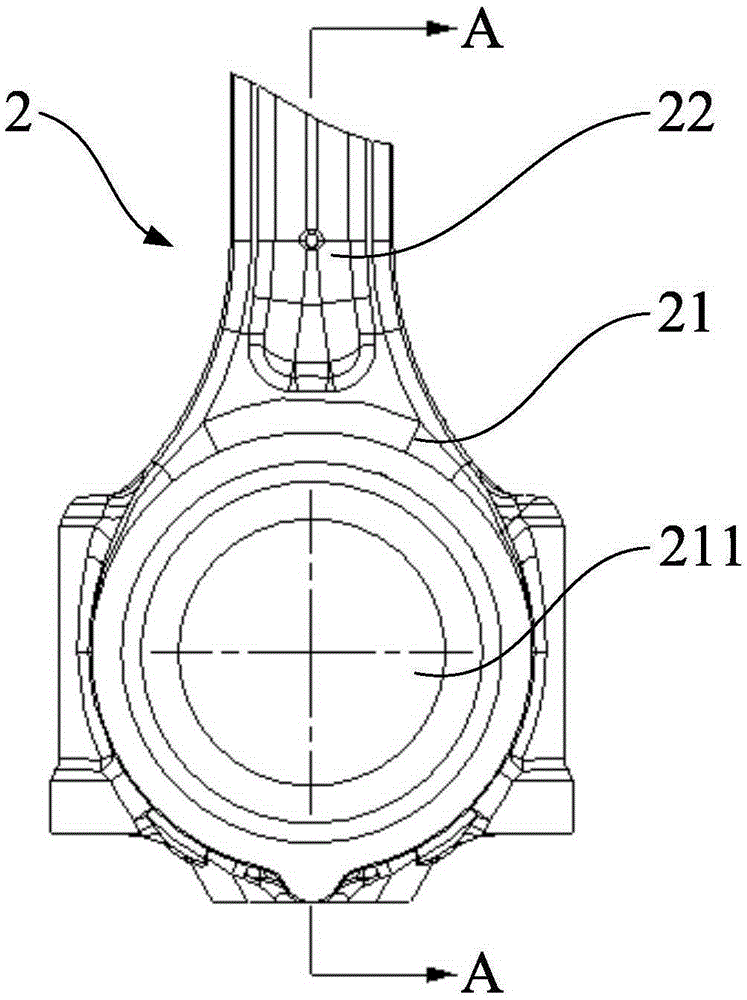
[0023] Figure 3 to Figure 4 The partial structure of the connecting rod mechanism 2 in the crankshaft connecting rod assembly according to the specific embodiment of the present invention is shown. Specifically, the link mechanism 2 includes a rod body 22 , a connecting rod small end (not shown) and a connecting rod large end 21 . Generally, the small end of the connecting rod is located at one end of the shaft 22, and t...


PUM


Abstract

The invention discloses a crankshaft connecting rod component. The crankshaft connecting rod component comprises a crank pin positioned on a crankshaft, and a connecting rod mechanism for connecting a piston with the crankshaft. The connecting rod mechanism comprises a rod body, a connecting rod small head and a connecting rod large head. The connecting rod small head is positioned at one end of the rod body; the connecting rod small head is provided with a small head pin hole; and the small head pin hole is connected with a piston pin of the piston. The connecting rod large head is positioned at the other end of the rod body, and is provided with a large head pin hole; the large head pin hole is connected with the crank pin; and the large head pin hole and the crank pin have one center shaft. A fit surface between the large head pin hole and the crank pin is a rotating curved surface with the center shaft as a rotating shaft, wherein the generatrix of the rotating curved surface is a circular arc; and the circle center of the circular arc is positioned on a vertical parting line of the center shaft. The crankshaft connecting rod component can increase a working area between the crank pin and the large head pin hole; and on the other hand, the edge structures of the crank pin and the large head pin hole are optimized to prevent the problem of edge stress concentration.

Description

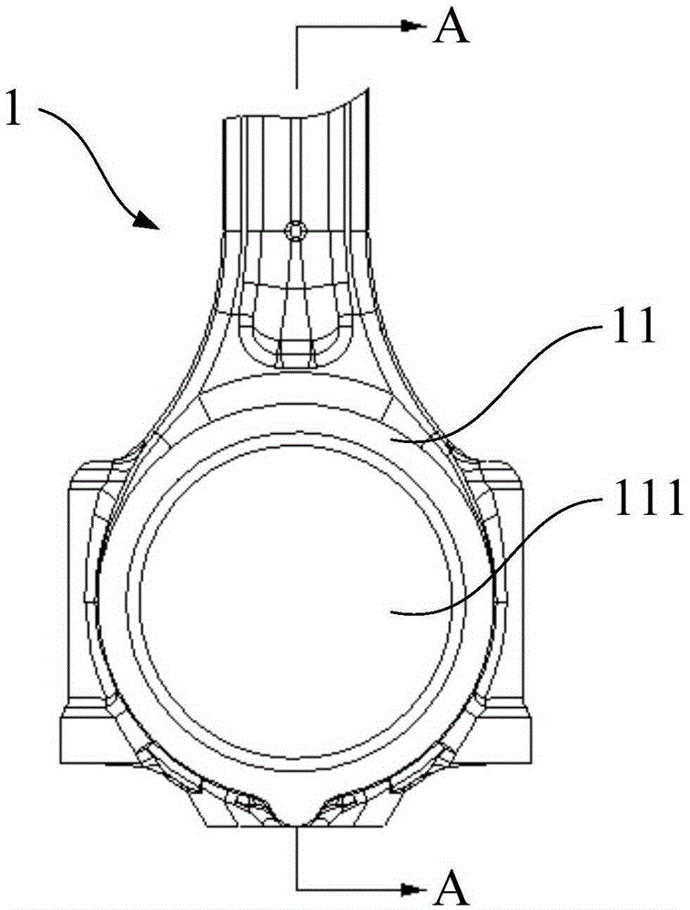
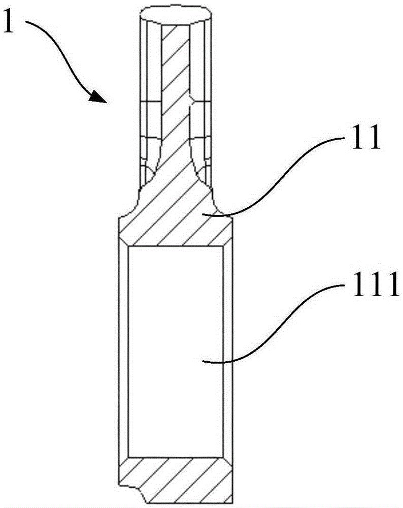
technical field [0001] The invention relates to the technical field of internal combustion engines, in particular to a crankshaft connecting rod assembly. Background technique [0002] The connecting rod mechanism of the internal combustion engine is used to connect the piston and the crankshaft, so that the reciprocating motion of the piston is converted into the rotary motion of the crankshaft. The connecting rod mechanism is one of the main motion bearing parts of the piston engine. The connecting rod mechanism generally includes the small end of the connecting rod, the shaft and the large end of the connecting rod. The small end of the connecting rod is used to install the piston pin to connect the piston; the large end of the connecting rod is matched with the crank pin of the crankshaft. In the prior art, such as figure 1 with figure 2 As shown, the connecting rod big end 11 of the connecting rod mechanism 1 (only partially shown) and the crank pin (not shown) of t...

Claims


Application Information

Patent Timeline
IPC IPC(8): F02B75/32F16C7/02
CPCF16C9/04F16C17/02
Inventor 陈彪吕昂覃星念谭达辉张锦蔚兴建
Owner GUANGXI YUCHAI MASCH CO LTD
Learn More