A Hall thruster anode

A technology of Hall thruster and anode, which is applied in the direction of thrust reverser, machine/engine, and utilization of plasma, etc. It can solve the problems of deposition coating, decrease of anode conductivity, large thermal load, etc., and achieve increased surface area and deposition coating phenomenon Reduction, the effect of heat load reduction

Active Publication Date: 2017-11-03
HARBIN INST OF TECH
View PDF5 Cites 0 Cited by
  • Summary
  • Abstract
  • Description
  • Claims
  • Application Information

AI Technical Summary

Problems solved by technology

[0004] The present invention aims to solve the problem that the anode structure of the existing Hall thruster has a large thermal load and serious deposition and coating phenomenon, which leads to a decrease in the electrical conductivity of the anode, and further provides an anode of the Hall thruster

Method used


Image

  • A Hall thruster anode
  • A Hall thruster anode
  • A Hall thruster anode

Examples


specific Embodiment approach 1

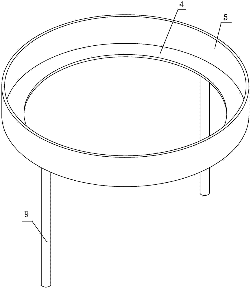
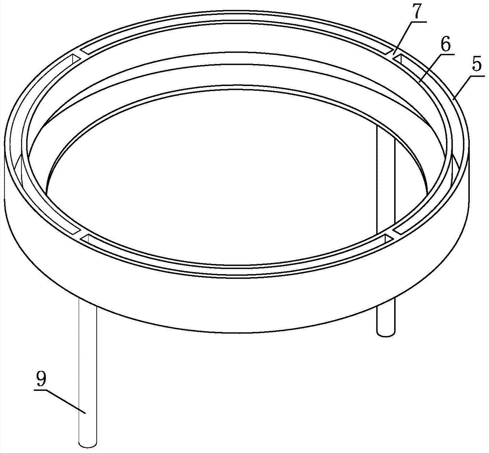
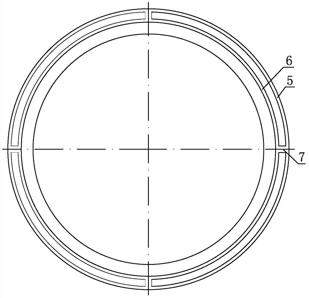
[0008] Specific implementation mode one: combine Figure 2-Figure 5 Explain that a Hall thruster anode in this embodiment includes a bottom ring 4 and a receiving ring 5 connected as one, and it also includes an inner ring 6, and an inner ring 5 having the same shape as the receiving ring 5 is fixed inside the receiving ring 5. The ring 6, the inner ring 6 and the receiving ring 5 form a circular concentric inner and outer double-ring structure, there is a gap between the outer surface of the inner ring 6 and the inner surface of the receiving ring 5, and the inner bottom surface of the inner ring 6 and the bottom ring 4 has a gap. gap.

specific Embodiment approach 2

[0009] Specific implementation mode two: combination Figure 2-Figure 5 Note that the upper end surface of the inner ring 6 in this embodiment is flush with the upper end surface of the receiving ring 5 . Such setting ensures that the position of the top of the anode does not exceed the position of the center line of the zero magnetic field zone during use, and the inner surface of the receiving ring 5 and the outer surface of the inner ring 6 can directly receive the magnetic field lines. Others are the same as in the first embodiment.

specific Embodiment approach 3

[0010] Specific implementation mode three: combination Figure 2-Figure 5 Note that the materials of the inner ring 6 and the receiving ring 5 in this embodiment are both metal molybdenum or non-magnetic stainless steel. Such setting, non-magnetic stainless steel material is used for low power, and molybdenum metal material is used for high power, which is beneficial to improve the thermal conductivity of the anode and reduce its own temperature. Others are the same as in the first or second embodiment.


PUM


Abstract

A Hall thruster anode, which relates to an electric propulsion Hall thruster, in order to solve the problem that the anode structure of the existing Hall thruster has a large thermal load and serious deposition and coating phenomenon, which leads to a decrease in the conductivity of the anode. It includes connections for An integrated bottom ring and receiving ring, which also includes an inner ring, the receiving ring is fixed with an inner ring of the same shape as the receiving ring, and the inner ring and the receiving ring form a circular concentric inner and outer double-ring structure; the outer surface of the inner ring and the receiving ring There is a gap between the inner sides of the rings, and there is a gap between the bottom surface of the inner ring and the inner bottom surface of the bottom ring. The invention is used for Hall thrusters.

Description

technical field [0001] The invention relates to an electric propulsion Hall thruster, in particular to an anode of the Hall thruster. Background technique [0002] Hall Effect Thruster (HET for short) is an electric thruster that uses orthogonal electromagnetic fields to ionize and accelerate atomic working fluids, convert electrical energy into ion kinetic energy, and obtain higher specific impulse. It has the characteristics of simple structure, high specific impulse, high efficiency, long working life, high power density, long service time in orbit, etc. It is suitable for attitude control, orbit correction, orbit transfer, power compensation, position maintenance, Repositioning, off-orbit processing, space exploration and interstellar voyage and other tasks are currently the most widely used and most mature electric propulsion systems in the world. [0003] The anode is an important component of the Hall thruster body, which is responsible for receiving electrons and fo...

Claims


Application Information

Patent Timeline
Patent Type & Authority Patents(China)
IPC IPC(8): F03H1/00
CPCF03H1/0075
Inventor 李鸿夏国俊丁永杰于达仁
Owner HARBIN INST OF TECH
Why Eureka
Try Eureka