
Wireless remote control microinjection device

A micro-injection, wireless remote control technology, applied in the direction of using electric device flow control, etc., can solve the problems of difficult to achieve networking and intelligence, complex manufacturing process, high price, etc., to achieve intelligent and networking, and simple control methods. , the effect of low cost

Active Publication Date: 2018-06-26
HARBIN INST OF TECH
View PDF6 Cites 0 Cited by
  • Summary
  • Abstract
  • Description
  • Claims
  • Application Information

AI Technical Summary

Problems solved by technology

[0003] The purpose of the present invention is to solve the problems of dead volume, large volume, high price, complex manufacturing process, and difficulty in realizing networking and intelligentization in the existing micro-flow system. The rapid prototyping technology combined with the wireless control technology proposes a wireless remote control micro-injection device

Method used


Image

  • Wireless remote control microinjection device
  • Wireless remote control microinjection device
  • Wireless remote control microinjection device

Examples


specific Embodiment approach 1

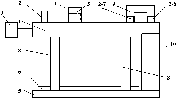
[0019] Specific implementation mode one: the following combination Figure 1 to Figure 6 Describe this embodiment, the wireless remote control micro-injection device described in this embodiment includes a liquid generating device 10, an air pressure source 11, a structural layer and a control layer; the air pressure source 11 provides gas for the structural layer; the structural layer and the control layer can be arranged up and down , connected by four supporting columns 8, the liquid generating device 10 is arranged between the structural layer and the control layer; the liquid generating device 10 is used to output the liquid for injection;

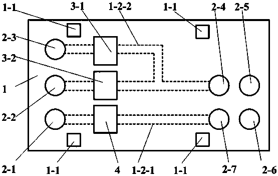
[0020] The structural layer includes a flow channel and base packaging module 1, a flow channel external joint 2, a microvalve drive unit 3, a flow sensor 4 and a hose 9; the flow channel and base packaging module 1 includes four support column installation holes 1 -1. Micro flow channel 1-2, concave film 1-3, flat film 1-4, flow chan...

specific Embodiment approach 2

[0029] Specific implementation mode two: combination Image 6 Referring to this embodiment, the liquid to be transported 10-5 in the wireless remote control micro-injection device can be medicine, nutrients, biological reagents, chemical reagents or water. Other connection relationships are the same as those in the first embodiment.

specific Embodiment approach 3

[0030] Specific implementation mode three: combination figure 1 with Figure 4 To illustrate this embodiment, the air pressure source 11 in the wireless remote control microinjection device can be a micro air pump, an air pump, an air compressor or a nitrogen tank. Other connection relationships are the same as those in the first embodiment.


PUM


Abstract

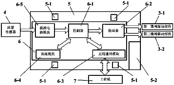
A wireless remote control micro-injection device belongs to the micro fluidic and medical injection fields, and aims at solving the problems that a present micro fluidic system has dead volume, and is large in size, high in cost, complex in manufacture technology and hard to be networked and intelligent. Pressure gas generated by a pneumatic source enters an h-shaped channel, is adjusted by a micro valve driving unit, and then enters a gas cavity of a liquid generation device. After the pressure of the gas cavity is increased, liquid to be transmitted is forced to be extruded outwardly, enters a linear channel, and is output to the outside through a flow sensor. The flow sensor measures flow signals of the output liquid, transmits the flow signals to a controller, the flow signals serve as feedback signals for system closed-loop control, and thus, the micro valve driving unit can adjust a valve in real time, and ensure the output characteristic of the system liquid. The controller communicates with a host computer via a wireless communication module, and the system can be controlled remotely wirelessly and monitored wirelessly.

Description

technical field [0001] The invention relates to a wireless remote control micro-injection device, which belongs to the field of microfluidic control and medical injection. Background technique [0002] Micro-flow systems are generally used for micro-fluid injection or delivery, and are used in medical, biochemical analysis, microfluidic chips and other fields. At present, the micro-flow systems widely used in the market are divided into three categories: peristaltic pump-type micro-flow systems, syringe pump-type micro-flow systems and pressure-type micro-flow systems. The peristaltic pump type micro-flow system has high control precision, but it has a large volume and complex implementation principles, and most of them cannot independently generate multiple flow outputs at the same time. Syringe pump micro-flow system has reliable performance and high control precision, but it is large in size and inevitably has dead volume in its cavity, so it is not suitable for the deli...

Claims


Application Information

Patent Timeline
Patent Type & Authority Patents(China)
IPC IPC(8): G05D7/06
Inventor 李松晶王进贤曾文符海杨天航
Owner HARBIN INST OF TECH
Learn More