
Machining tool for artificial floors

An artificial floor and tooling technology, applied in the field of artificial floor processing tooling, can solve the problems of inability to adjust the width of cutting boards, inconvenience, and non-adjustable spacing, etc., achieve the best cache and release effect, enhance applicability, and avoid blade breakage Effect

Inactive Publication Date: 2016-01-27
万世蓉
View PDF11 Cites 0 Cited by
  • Summary
  • Abstract
  • Description
  • Claims
  • Application Information

AI Technical Summary

Problems solved by technology

Furthermore, the existing cutting machines for processing plates generally only have two cutting knives, and the distance between the two cutting knives cannot be adjusted, so that the width of the cutting plate cannot be adjusted. In this case, the staff can only It is inconvenient to choose cutting machines of different specifications and models for cutting

Method used


Image

  • Machining tool for artificial floors
  • Machining tool for artificial floors
  • Machining tool for artificial floors

Examples


Embodiment 1

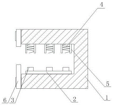
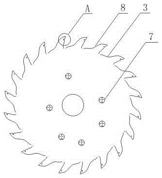
[0024] Such as figure 1 , figure 2 , image 3 As shown, a processing tool for artificial flooring includes a working body 1 whose side surface opening is a cavity structure, a punch platform 2 arranged on the bottom of the inner cavity of the working body 1, and several cutting knives arranged on the punch platform 2 3; a spring 4 is installed at the upper part of the inner cavity of the working body 1 corresponding to the position of the cutter 3; it also includes guide columns 5 arranged on both sides of the spring 4 and a feeding sleeve 6 sleeved at the opening of the side surface of the working body 1, the The guide post 5 is fixed on the upper part of the inner cavity of the working body 1 .

[0025] In this embodiment, when the floor is to be cut, the floor is placed in the cavity of the working body 1, and the feeding sleeve 6 plays a role in fixing the floor, so as to avoid cutting errors caused by shaking of the floor during the cutting process. . After the floor...

Embodiment 2

[0027] In this embodiment, on the basis of Embodiment 1, one or more through holes 7 are opened on the cutting surface of the cutting knife 3 . The through hole 7 is filled with polymer sound-absorbing material.

[0028] The sound-absorbing material arranged in the through hole 7 is used to absorb noise during the cutting process of the cutter, reduce the sound pressure value, and avoid damage to the worker's body due to excessive noise during operation.

Embodiment 3

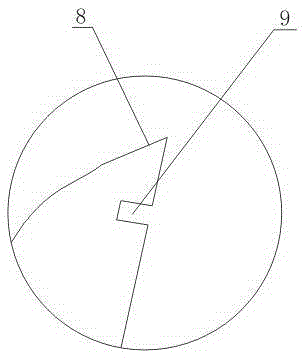
[0030] In this embodiment, on the basis of Embodiment 1 or Embodiment 2, several serrated blades 8 are arranged on the edge of the cutting knife 3 , and grooves 9 are opened on the side walls of the blades 8 along the direction from the edge to the back of the blade.

[0031] In this embodiment, the groove 9 provided on the blade 8 along the direction from the blade edge to the back of the blade enables buffering and release of the impact stress suffered by the cutting knife 3 during the cutting process, preventing the blade 8 from breaking due to excessive stress concentration.


PUM


Abstract

The invention discloses a machining tool for artificial floors. The machining tool comprises a tool body, a punch press platform and a plurality of cutters, wherein the side surface of the tool body is open, the tool body is of a cavity structure, the punch press platform is arranged at the bottom of the inner cavity of the tool body, and the cutters are arranged on the punch press platform. Springs are mounted at the positions, corresponding to the cutters, of the upper portion of the inner cavity of the tool body. The machining tool further comprises guiding columns and a feeding sleeve, wherein the two sides of each spring are each provided with the corresponding guiding column, and the feeding sleeve is arranged at the opening of the side surface of the tool body in a sleeving mode. The guiding columns are fixed on the upper portion of the inner cavity of the tool body. According to the machining tool, the cutting width is adjustable through the arrangement of the punch press platform and the cutters, so that the adaptability of machining equipment is enhanced. The feeding sleeve plays a role of floor fixing, and cutting errors caused by shaking of the floors in the cutting process are avoided. The springs mounted at the positions, corresponding to the cutters, of the upper portion of the inner cavity of the tool body play a role of resetting on the cutters.

Description

technical field [0001] The invention relates to processing equipment, in particular to a processing tool for artificial flooring. Background technique [0002] As people have higher and higher requirements for the strength of wooden floors used in family houses, artificial flooring has developed rapidly in recent years. In the process of installing artificial floors, construction workers often need to use cutting equipment to cut large-size panels into various required small sizes. This kind of cutting is not only a lot of work, but also due to the high hardness and brittleness of artificial floors. During the processing, the cutting tool is often broken due to the concentrated force on the tip of the blade after being subjected to impact force, so that the service life of the cutting tool is short, and in severe cases, the broken fragments will fly out and hurt workers. Furthermore, the existing cutting machines for processing plates generally only have two cutting knives,...

Claims


Application Information

Patent Timeline
Patent Type & Authority Applications(China)
IPC IPC(8): B27B5/06B27B5/29B27B29/02B27B5/38B27B33/08B27G19/02
Inventor 万世蓉
Owner 万世蓉
Learn More