A dual cooling system for supercharged and miniaturized engines

A cooling system and engine technology, applied in the direction of engine cooling, engine components, machines/engines, etc., can solve the problems of difficult layout, complex calculation of heat damage, slow response, etc., to improve cooling effect, ensure air intake efficiency, The effect of ensuring the intake air temperature

Active Publication Date: 2017-09-19
ANHUI JIANGHUAI AUTOMOBILE GRP CORP LTD
View PDF12 Cites 0 Cited by
  • Summary
  • Abstract
  • Description
  • Claims
  • Application Information

AI Technical Summary

Problems solved by technology

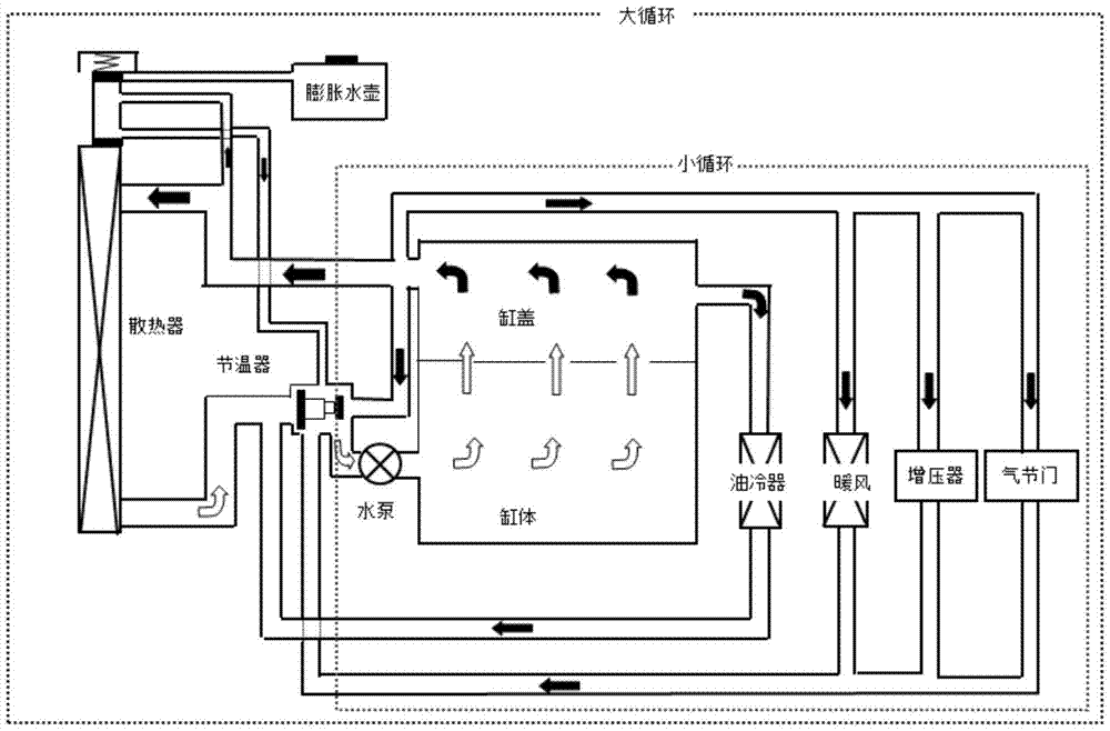
[0005] In the large cycle state of the traditional engine cooling system, there is only one main circuit. With the continuous promotion of engine fuel-saving technology, the number of components integrated on the engine is gradually increasing, such as intercooler, BSG, electronic supercharger, etc. These The new integrated components also need to be cooled, but the cooling temperature, flow rate and control logic required are completely different from those of the engine block and cylinder head; therefore, the traditional cooling control loop can no longer meet the application of new technologies
[0006] In addition, the traditional mechanical thermostat responds slowly, and its opening and closing are determined by the water temperature of the engine, which is not conducive to the warm-up of the engine and the rapid cooling of the water temperature
[0007] The existing technology proposes to use air-cooling technology for the intercooler, BSG and electronic supercharger, but the air-cooling has high requirements for space and the layout of the entire engine compartment, which is difficult to arrange, and the calculation of heat damage is complicated. The risk is high, and it generally requires repeated improvements to achieve the desired effect. In addition, the environment of the vehicle is changeable, making it difficult for the air-cooling system to meet the needs of various operating conditions in various environments.

Method used


Image

  • A dual cooling system for supercharged and miniaturized engines
  • A dual cooling system for supercharged and miniaturized engines

Examples


Embodiment Construction

[0041] The technical solution of the present invention is described in detail below through the examples, and the following examples are only exemplary and can only be used to explain and illustrate the technical solution of the present invention, rather than being interpreted as a limitation to the technical solution of the present invention.

[0042] Definition of key components

[0043] BSG: (Belt Starter Generator) A belt starter generator system: it can realize the engine start / stop function, realize energy recovery, auxiliary torque increase and other functions.

[0044] Electronic supercharger: (Electric Super-Charger ESC) is an electronic matching product that can improve the ignition and combustion state of the automobile engine. Its main function is to improve the low-end torque and torque responsiveness of the engine. The speed of the motor is dragged to 70,000 rpm, and air is needed to cool the motor, which is integrated inside the air filter.

[0045] Electronic wa...


PUM


Abstract

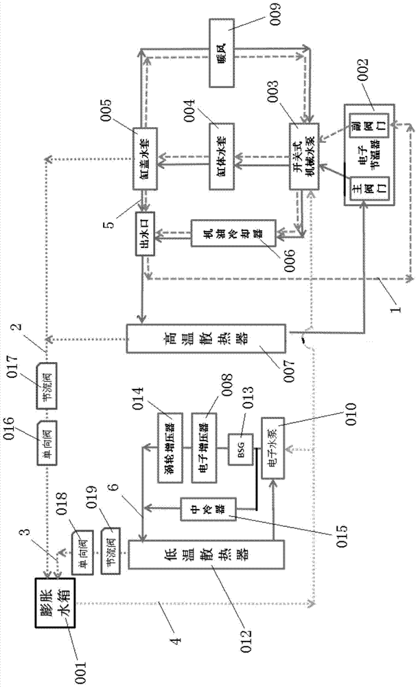
The invention relates to a supercharging miniaturized engine dual-cooling system which comprises a high-temperature circulation cooling system and a low-temperature circulation cooling system. The high-temperature circulation cooling system comprises an expansion water tank, a high-temperature cooler, an engine cooling water jacket, a first water pump, an electronic thermostat, an oil cooler and an air heater. The low-temperature circulation cooling system comprises the expansion water tank, a low-temperature cooler, a turbocharger, a second water pump, an intercooler, a BSG and an electronic supercharger. The two circulation cooling systems are arranged, the high-temperature cooler and the low-temperature cooler are arranged, and therefore the requirements of different components to be cooled for cooling temperature are effectively guaranteed. According to the technical scheme, the size of the cooling systems is not increased. Meanwhile, parallel connection of series-connection branches of the BSG, the turbocharger and the electronic supercharger and branches of the intercooler is adopted in the low-temperature circulation cooling system, and stability of the pressure difference of the components is guaranteed.

Description

technical field [0001] The invention belongs to the field of automobile cooling systems, and specifically refers to a dual cooling system for supercharged miniaturized engines. Background technique [0002] Governments of various countries have promulgated more and more stringent standards for engine fuel consumption. For example, it is stipulated that automobile OEMs will continue to reduce fuel consumption to 5.0L / 100km in 2020; One technology is the supercharged miniaturization of the engine + hybrid technology. [0003] In response to local government regulations, a more innovative engine matching system must be found to accomplish this goal. Because on the premise of not losing power, it is basically an impossible task to reduce fuel consumption by 30% on the current basis. Therefore, it is proposed to use a hybrid power system + electronic supercharging on the engine, and achieve the requirement of reducing fuel consumption through weak mixing and miniaturization of ...

Claims


Application Information

Patent Timeline
Patent Type & Authority Patents(China)
IPC IPC(8): F01P3/20F01P7/16F01P11/00
Inventor 杨栋陈强曹维维李玉森李海亮翟晓红殷红敏翁锐
Owner ANHUI JIANGHUAI AUTOMOBILE GRP CORP LTD
Why Eureka
Try Eureka