
Transparent cable difficult to discern and easy for indoor wiring

An indoor wiring and transparent technology, applied in the field of cables, can solve the problems of poor resistance to torsion and flexure, thick sheath, poor bending resistance, etc., to reduce resistance and difficulty, high user acceptance, The effect of quick and convenient wiring

Inactive Publication Date: 2016-01-27
CHINA INFOMRAITON CONSULTING & DESIGNING INST CO LTD
View PDF6 Cites 2 Cited by
  • Summary
  • Abstract
  • Description
  • Claims
  • Application Information

AI Technical Summary

Problems solved by technology

[0003] First of all, the diameter of the traditional indoor optical cable is relatively thick, and the radius of the commonly used indoor optical cable is about 2mm-3mm
Secondly, the outer sheath of traditional indoor optical cables mainly uses polyethylene sheath or low-smoke halogen-free flame-retardant polyolefin sheath. The sheath is thicker and the color of the sheath is more obvious, mainly black or yellow. In indoor wiring It is particularly conspicuous. Moreover, after the optical cable is unsheathed, the colored coating layer structure of the optical fiber will destroy the overall appearance of the interior for users who have not reserved a dark groove for wiring in advance.
Thirdly, due to the limitation of structure and shape, the traditional indoor optical cable itself has a strengthening member, its bending radius is relatively small, the bending resistance is not good, and the torsion and bending resistance are also poor.
In addition, due to the heavy weight of traditional indoor optical cables, when laying indoors, it is necessary to adopt the traditional laying method of nailing along the wall. The construction is relatively difficult. For users, the nailing method also destroys the indoor wall. This is a very troublesome thing for many users. It has also become a part of the contradiction between the construction party and users in the process of operator business development, and it has also become an important factor restricting the operator's business expansion. factor

Method used


Image

  • Transparent cable difficult to discern and easy for indoor wiring
  • Transparent cable difficult to discern and easy for indoor wiring

Examples


Embodiment

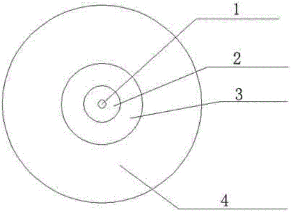
[0020] Such as figure 1 The cable of the present invention includes a cable core 1 located inside, and the outer ring of the cable core 1 is coated with a cladding 2, a coating 3 and a protective layer 4 in sequence. In this embodiment, the cladding is 125um thick, and the coating The thickness is 250um, and the protective layer is made of transparent thermoplastic elastomer, with a thickness of 900um.

[0021] (1) Basic structure of optical cable

[0022] The selection of optical cable materials and structures should be suitable for the intended use and installation conditions. The optical cable sheath should be made of transparent thermoplastic. The optical cable should have good transparency, and there is no obvious color difference between the optical fiber and the sheath.

[0023] (2) Typical size of optical cable

[0024] The typical structural size of the optical cable should meet 0.9mm (tolerance 0.05mm).

[0025] (3) Requirements for optical fibers in optical cable...


PUM


Abstract

The invention provides a transparent cable which is difficult to discern and is easy for indoor wiring. The cable comprises a cable core. The outer ring of the cable core is coated from inside to outside with a cladding layer, a coating layer and a protecting layer successively. The coating layer and the protecting layer are made of transparent material. The coating layer is made of UV-curable acrylate resin. The protecting layer is made of transparent thermoplastic elastomer. The number of the cable core is one. Due to the light self-weight, wiring can be performed by bonding with glue. The wiring is quick and easy and produces little noise disturbance. The influence on wall body by the wiring method is reduced to the minimum so that the disturbance on users is reduced to the minimum. The user acceptance level is high. Thus, the resistance and difficulty of indoor wiring of service providers are greatly reduced and a multi-win effect is achieved.

Description

technical field [0001] The invention relates to a cable, in particular to a transparent and hard-to-see cable for indoor wiring. Background technique [0002] With the continuous development of optical fiber communication technology, as well as the continuous maturity and improvement of the optical fiber and communication peripheral industry chain, the scale of optical fiber communication network continues to expand. In recent years, telecom operators are building FTTH networks on a large scale. At the same time, there are a large number of group Customer and common customer access issues. Traditional lead-in optical cables have shown good advantages when they are routed in indoor dark grooves; but if users do not reserve pipe grooves or dark pipes in advance, how can optical cables be integrated into the indoor environment effectively and beautifully without damaging users or groups when wiring indoors? The aesthetics of the overall decoration of the customer's office has ...

Claims


Application Information

Patent Timeline
Patent Type & Authority Applications(China)
IPC IPC(8): G02B6/44
CPCG02B6/443
Inventor 杨红伟吴煜赵捷徐梅香王睿揭水平张敏锋李永嫚
Owner CHINA INFOMRAITON CONSULTING & DESIGNING INST CO LTD
Learn More