Zinc-manganese flow battery

A flow battery, zinc-manganese technology, applied in the direction of alkaline storage batteries, alkaline storage battery electrodes, etc., can solve problems such as cross-contamination costs, achieve long cycle life, simple structure and manufacturing process, and solve cross-contamination effects.

A flow battery, zinc-manganese technology, applied in the direction of alkaline storage batteries, alkaline storage battery electrodes, etc., can solve problems such as cross-contamination costs, achieve long cycle life, simple structure and manufacturing process, and solve cross-contamination effects.

CN105280964AActive Publication Date: 2016-01-27DALIAN INST OF CHEM PHYSICS CHINESE ACAD OF SCI

Image

  • Zinc-manganese flow battery
  • Zinc-manganese flow battery

Examples


Embodiment

[0022] Electrolyte configuration:

[0023] Electrolyte: Electrolyte 40ml, which contains 1.0moldm -3 MnSO 4 , 1 mold m -3 ZnSO 4 , 0.2moldm -3 h 2 SO 4 .

[0024] Battery Assembly:

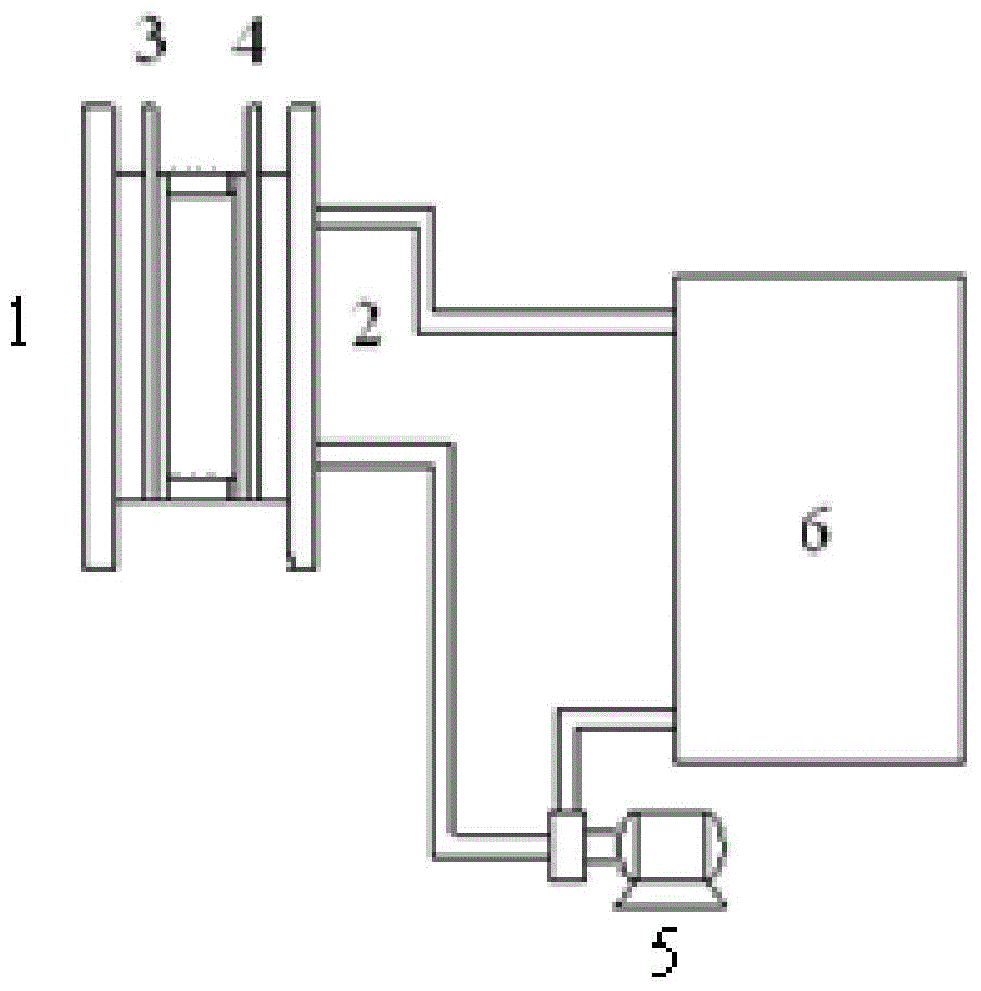
[0025] Positive terminal plate, positive electrode 3x3cm in order of single cell 2 Nickel foam, negative electrode 3x3cm 2 Nickel foam, negative terminal plate. Single battery structure and system see figure 1 .

[0026] Battery test:

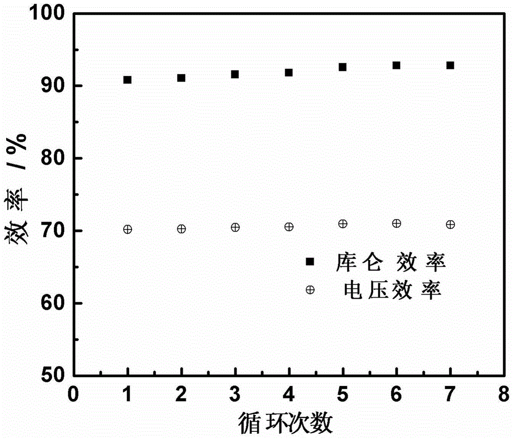
[0027] Electrolyte flow rate: 5ml / min; charge and discharge current density 10mA / cm 2 ; Charging for 1h, the discharge cut-off voltage is 0V. For battery performance see figure 2 , from the charge-discharge current density figure 2 It can be seen that at 10mA / cm 2 ; The charging time is 1h, and the average energy efficiency of the battery reaches about 70%.


PUM


Abstract

The invention relates to a zinc-manganese flow battery. The battery comprises a battery module, an electrolyte storage tank, a circulating pump and a circulation pipeline, wherein the battery module is formed by connecting a single battery or more than two single batteries in series, the single battery comprises a positive electrode and a negative electrode, the positive electrode and the negative electrode are oppositely arranged, a gap is reserved between the positive electrode and the negative electrode, and an electrolyte is an acidic aqueous solution containing divalent zinc ions and divalent manganese ions. In the battery, solid-liquid phase conversion is adopted during the reaction of the positive electrode and the negative electrode, a diaphragm is not needed, only one electrolyte loop is needed, the problem of cross contamination of the traditional flow battery is solved, and the zinc-manganese flow battery has the characteristics of long cycle lifetime, low cost and simplicity in structure and manufacturing process.

Description

technical field [0001] The invention relates to a zinc-manganese liquid flow battery, which can be widely used in the fields of electronics industry, transportation, mining and metallurgy, and the like. Background technique [0002] With the continuous increase of population and the improvement of living standards, people's demand for energy is soaring. Traditional fossil energy will not be able to meet people's needs in the near future. Therefore, the development and utilization of renewable energy such as wind energy and solar energy are subject to extensive attention. However, these renewable energy sources are discontinuous, unstable, restricted by regional environment, and difficult to connect to the grid, resulting in low utilization rate, high wind and light abandonment rate, and waste of resources. Energy storage technology can improve the utilization rate and stability of renewable energy through the storage and release of capacity, and is a key technology for the ...

Claims


Application Information

Patent Timeline
27 Jan 2016
Publication
CN105280964A
IPC
H01M10/24; H01M4/24
CPC
Y02E60/10
Inventors
张华民; 程元徽