Switch power supply protection and control method and circuit

A switching power supply and protection control technology, applied in emergency protection circuit devices, electrical components, output power conversion devices, etc., can solve the problems of startup circuit loss, chip power consumption and heat generation, etc. Reliability, the effect of reducing power consumption

Active Publication Date: 2016-01-27
MORNSUN GUANGZHOU SCI & TECH
View PDF7 Cites 8 Cited by
  • Summary
  • Abstract
  • Description
  • Claims
  • Application Information

AI Technical Summary

Problems solved by technology

In addition, most of the protection at this stage is to pull down the FB pin or Comp pin of the chip, and after this pin

Method used


Image

  • Switch power supply protection and control method and circuit
  • Switch power supply protection and control method and circuit
  • Switch power supply protection and control method and circuit

Examples


Embodiment 1

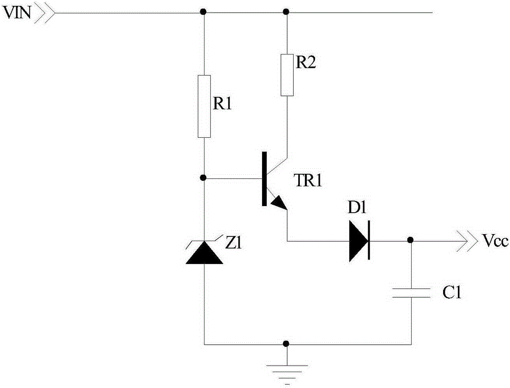
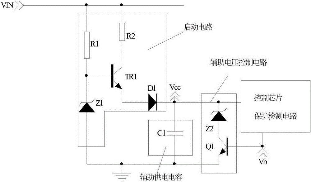
[0039] figure 2 It is a circuit diagram of one of the specific embodiments of the present invention. The circuit is composed of a starting circuit, an auxiliary voltage control circuit, an auxiliary power supply capacitor, a control chip and a protection detection circuit, wherein the starting circuit and the auxiliary power supply capacitor and figure 1 Exactly the same, the auxiliary voltage control circuit is composed of the second voltage regulator tube Z2 and the second triode Q1, which are connected in parallel with the auxiliary power supply capacitor, specifically: the cathode of the second voltage regulator tube Z2 is connected to the cathode of the first diode D1 , the anode of the second voltage regulator tube Z2 is connected to the collector of the second transistor Q1, the emitter of the second transistor Q1 is connected to the ground, the base of the second transistor Q1 is connected to the control chip and the protection detection circuit composed system connec...

Embodiment 2

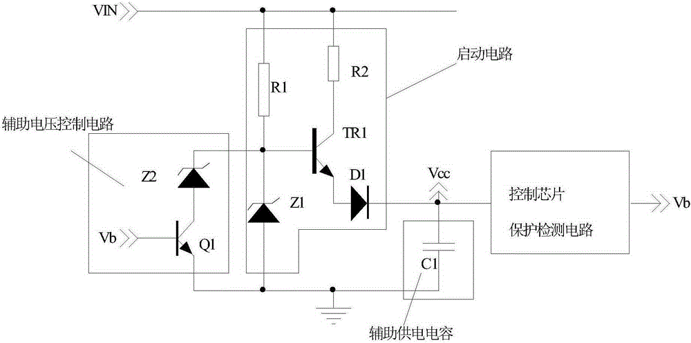
[0042] Such as image 3 It is the circuit diagram of Embodiment 2 of the present invention. The difference from Embodiment 1 is that the auxiliary voltage control circuit is connected in parallel with both ends of the first voltage regulator tube Z1 of the start-up circuit. Its basic working process is consistent with Embodiment 1. When the protection detection circuit outputs the control signal Vb at a high level, the base of the second transistor Q1 of the auxiliary voltage control circuit is at a high level, the second transistor Q1 is turned on, and the second voltage regulator transistor Z2 is turned on. The voltage regulation value Vz2 of the second voltage regulator tube Z2 is smaller than the voltage regulator value of the first voltage regulator tube Z1, so the first voltage regulator tube Z1 stops working, and the auxiliary power supply voltage Vcc=Vz2-Vbe-Vd1, also realizes the protection of the real-time example 1 Effect. When the circuit exits the protection mode...

Embodiment 3

[0044] Such as Figure 4 It is the circuit diagram of the third embodiment of the present invention. The difference between it and the second embodiment is that the second triode of the auxiliary voltage control circuit is replaced by the first control chip U1, the first control chip is a 431 control chip, and the first control chip U1 The cathode is connected to the anode of the second regulator tube Z2, the anode of the first control chip U1 is connected to the ground, and the reference terminal of the first control chip U1 is connected to the protection detection circuit. The working process of the third embodiment is consistent with the working process of the second embodiment, and will not be described in detail here.


PUM


Abstract

The invention discloses a switch power supply protection and control method. The switch power supply protection and control method can adjust the voltage of an auxiliary power supply by detecting the working state of a main power circuit of a switch power supply; and when the circuit is under the protection state, the voltage of the auxiliary power supply is reduced below the turn-off voltage of a main control chip of the circuit. The invention also provides a switch power supply protection and control circuit using the method. The switch power supply protection and control method and circuit can solve the problem that a dead lock situation occurs when the control chip of the switch power supply exits the protection, and can effectively solve the problem that the auxiliary power supply is not stable when an existing switch power supply is under the protection state, and can solve the loss generated by excessively high voltage of the auxiliary power supply during the protection process, and can solve the transient abnormity for an existing hiccup type protection for the switch power supply, and can improve the reliability of the entire design of the product.

Description

technical field [0001] The invention relates to a switching power supply protection control method and circuit, in particular to a control method and a circuit for an auxiliary power supply of a switching power supply when the switching power supply has overvoltage protection, undervoltage protection, short circuit protection, overtemperature protection and other protections. Background technique [0002] With the development of the power electronics industry, the traditional linear power supply is gradually replaced by the switching power supply with switching characteristics. The switching power supply has the advantages of high efficiency and high reliability. After years of development, different circuit topologies have appeared in switching power supplies, including forward topology, flyback topology, etc., as well as push-pull topology and bridge topology evolved from forward topology. Different topologies have their own advantages. At the same time, with the continuou...

Claims


Application Information

Patent Timeline
IPC IPC(8): H02H7/12H02M1/00
Inventor 开秋月金若愚朱培鸿
Owner MORNSUN GUANGZHOU SCI & TECH
Why Eureka
Try Eureka