Signal decoding unit based on FPGA (Field Programmable Gate Array) and DSP (Digital Signal Processor) and realization method for signal decoding unit based on FPGA and DSP

A technology of decoding unit and implementation method, which is applied in the field of signal decoding, can solve problems such as slow rate and complex interface protocol, and achieve the effects of improving flexibility, high transmission rate, and simplifying system design

Active Publication Date: 2016-01-27
中国船舶重工集团公司第七二六研究所
View PDF5 Cites 17 Cited by
  • Summary
  • Abstract
  • Description
  • Claims
  • Application Information

AI Technical Summary

Problems solved by technology

In the past, the ATM protocol was often used for the transmission of this decoded signal. Although it also uses optical fiber, the rate is relatively slow and the interface protocol is relatively complicated, which are unfavorable factors for signal decoding and data transmission of multi-extension systems.

Method used


Image

  • Signal decoding unit based on FPGA (Field Programmable Gate Array) and DSP (Digital Signal Processor) and realization method for signal decoding unit based on FPGA and DSP
  • Signal decoding unit based on FPGA (Field Programmable Gate Array) and DSP (Digital Signal Processor) and realization method for signal decoding unit based on FPGA and DSP
  • Signal decoding unit based on FPGA (Field Programmable Gate Array) and DSP (Digital Signal Processor) and realization method for signal decoding unit based on FPGA and DSP

Examples


Embodiment Construction

[0041] The present invention will be described in detail below in conjunction with specific embodiments. The following examples will help those skilled in the art to further understand the present invention, but do not limit the present invention in any form. It should be noted that those skilled in the art can make several modifications and improvements without departing from the concept of the present invention. These all belong to the protection scope of the present invention.

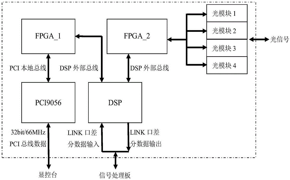
[0042] The purpose of the present invention is to provide a method for realizing an efficient multi-channel signal decoding unit based on FPGA+DSP cooperative work. The realization process of the present invention is such: at first by CPCI bus line, parameter update order is written into DSP internal memory, is written in the storage FIFO of FPGA by DSP through external bus line, parameter data is sent out by multi-channel photoelectric conversion module at last; After the synchronization command,...


PUM


Abstract

The invention provides a signal decoding unit based on a FPGA (Field Programmable Gate Array) and a DSP (Digital Signal Processor) and a realization method for the signal decoding unit based on the FPGA and the DSP. The signal decoding unit comprises a signal decoding board card, a FPGA module, a PCI interface chip, a DSP module and an optical communication module. The FPGA module, the PCI interface chip, the DSP module and the optical communication module are arranged on the signal decoding board card. The FPGA module is connected with the PCI interface chip and the DSP module through a bus. The PCI interface chip is connected to a display console through a PCI bus. The DSP module is connected to an external signal processing board through a LINK port. The FPGA module receives and sends an optical signal through the optical communication module. The system adopted by the method is simple in structure, a large-scale integrated chip is adopted, multiple-channel processing is adopted, the system design is simplified, and advantages of long transmission distance, strong anti-interference capability, low storage resource consumption, stable and reliable data format conversion, high transmission efficiency and the like are achieved.

Description

technical field [0001] The invention relates to the field of signal decoding, in particular to a signal decoding unit based on an FPGA and a DSP platform and an implementation method thereof. Background technique [0002] With the development of digital systems, long-distance transmission of large-capacity data and effective encoding and decoding of data have become important issues in system design. With the signal decoding unit as the core of data transmission, Ethernet technology and photoelectric conversion modules are used to build an Ethernet interface hardware platform suitable for large-scale data transmission, which can not only improve communication quality, but also simplify system wiring. A good solution with wide application prospects. [0003] The commonly used general-purpose signal decoding unit has a low transmission rate and does not have the ability to decode multi-channel signals. However, when the complexity of project design increases and data integrat...

Claims


Application Information

Patent Timeline
Patent Type & Authority Applications(China)
IPC IPC(8): H03M13/00
Inventor 任娟曾武吴楚楚
Owner 中国船舶重工集团公司第七二六研究所
Why Eureka
Try Eureka