Interbody fusion cage and implantation device thereof

A technology of intervertebral body and fusion device, which is applied in the direction of joint implants, joint implants, spinal implants, etc. It can solve the problems of unsatisfactory recovery of patients and achieve good surgical results, less damage and stable structure Effect

Inactive Publication Date: 2016-02-03
上海祥尧医疗器械有限公司
View PDF12 Cites 6 Cited by
  • Summary
  • Abstract
  • Description
  • Claims
  • Application Information

AI Technical Summary

Problems solved by technology

In several cases, the recovery of patients with intervertebral fusion cages pl

Method used


Image

  • Interbody fusion cage and implantation device thereof
  • Interbody fusion cage and implantation device thereof
  • Interbody fusion cage and implantation device thereof

Examples


Embodiment 1

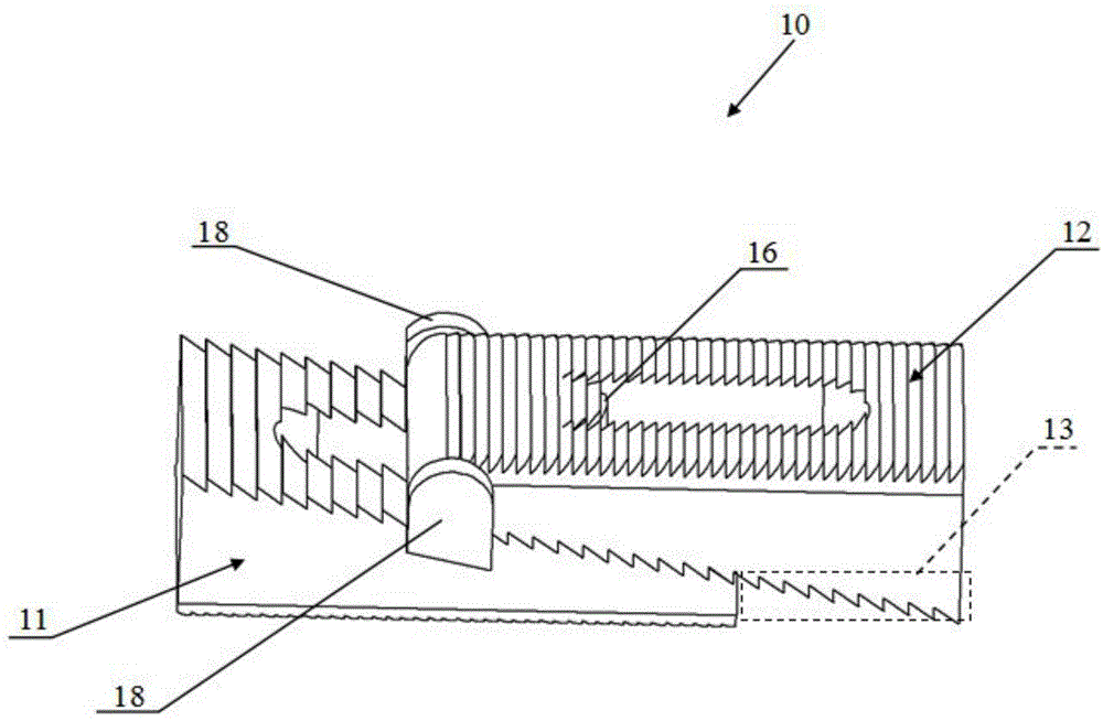
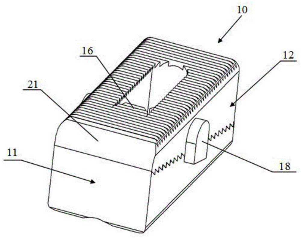
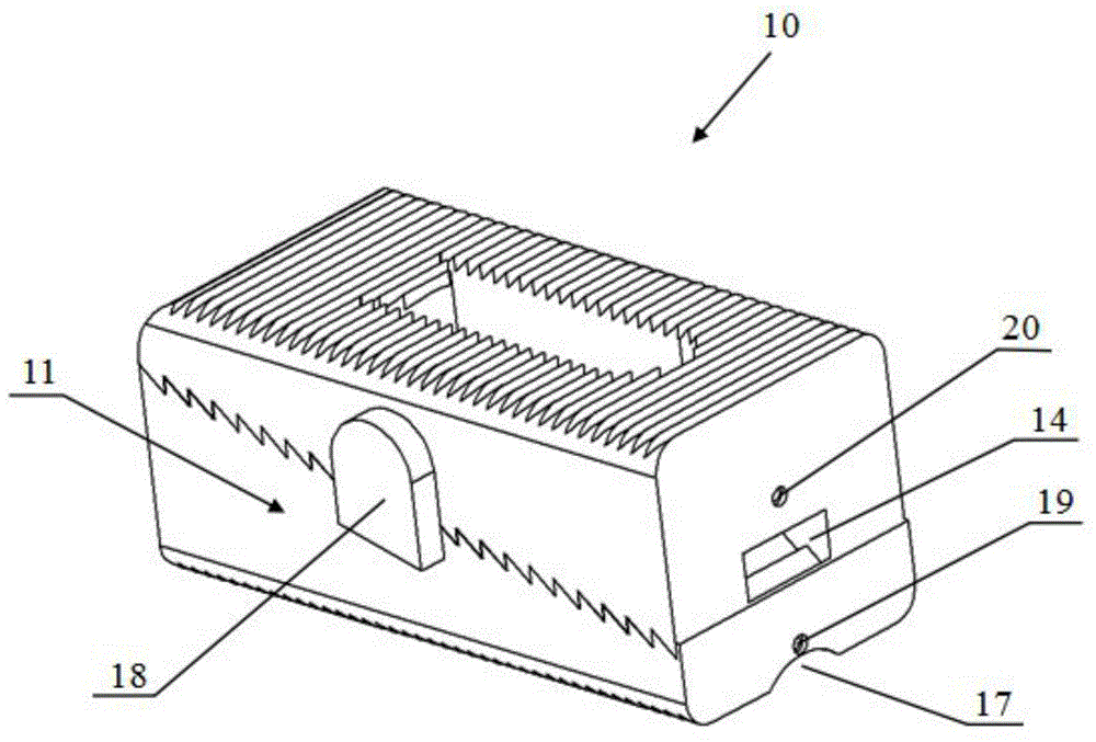
[0039] figure 1 It is an oblique view of the interbody fusion device of the present invention during installation. Such as figure 1 As shown, the interbody fusion device 10 includes a first implant component 11 and a second implant component 12, both of which are in the shape of a trapezoid. The two first stoppers 13 have inverted tooth structures capable of engaging with each other, and are respectively located on the opposite surfaces of the first implant member 11 and the second implant member 12, and the two first stoppers 13 are respectively located on the first implant member 11 and the second implant member 12. The implant member 11 and the second implant member 12 are integrally formed. The shape of the inverted tooth on the first stopper 13 is a triangle, and one of the sides of the triangle is tilted forward, and the other side is vertically downward, so that when the first implant member 11 is implanted into two vertebrae Between the body, the inclined forward ed...

Embodiment 2

[0052] For the same structures as those in the first embodiment, the second embodiment gives the same numbers and omits the same descriptions.

[0053] Such as Figure 5 and Figure 6 As shown, the shape of the cross-section of the first implant member 41 and the second implant member 42 of the intervertebral fusion device 40 in this embodiment is a shape with narrow ends and a wide middle, and this shape is hereinafter referred to as wine Barrel.

[0054] Such as Figure 5 As shown, the interbody fusion device 40 includes a first implant member 41 and a second implant member 42, and two third stoppers 45 are in the shape of circular arc-shaped upper ends, and are arranged on the first implant member 11. sides and extend upwards. Figure 5 is not shown in the image 3 The structure of the groove 14 in the corresponding position. Such as Figure 6 As shown, the two third stoppers 45 are located in front of the widest part of the barrel-shaped middle, and being set at thi...

Embodiment 3

[0058] This embodiment provides another embodiment of the interbody fusion device of the present invention. Other structures of the implant component in this embodiment, such as the guide post and the inverted tooth structure on the upper and lower surfaces, are the same as those in the previous embodiments. Only the parts different from the above two embodiments will be described below.

[0059] Figure 10 It is the rear view of the intervertebral fusion device of the present invention in Embodiment 3; and Figure 11 It is an oblique view of the third embodiment of the interbody fusion device of the present invention.

[0060] Such as Figure 10 and Figure 11 As shown, it can be seen from the rear view of the intervertebral fusion device 50 that when the left and right sides of the first implant member 51 and the second implant member 52 are in the shape of an arc protruding outward, it is similar to the intervertebral foramen The cylindrical shape of the lens, the arc ...


PUM


Abstract

The invention provides an interbody fusion cage and an implantation device thereof. The interbody fusion cage is implanted between two adjacent vertebrae of a vertebral column to replace an intervertebral disc issue in degeneration and protrusion so as to recover and keep a normal vertebral clearance height. The interbody fusion cage is characterized by comprising a supporting component and a limiting part, the supporting component is used for supporting the vertebrae, and the limiting part is connected with the supporting component and used for limiting the supporting component; the supporting component is formed by matching a first implantation member with a second implantation member, and the limiting part limits longitudinal and bilateral relative displacement between the first implantation member and the second implantation member after matching is finished. By adoption of a design that the first implantation member and the second implantation member are combined to form a whole implant, thicker interbody fusion cages can be implanted by the aid of an existing 8mm intervertebral foramen endoscope without use of intervertebral foramen endoscopes with larger diameters, and accordingly injuries to patients are reduced.

Description

technical field [0001] The invention relates to an intervertebral fusion device, and also relates to an implanting device for implanting the intervertebral fusion device. Background technique [0002] Intervertebral discs are located between adjacent vertebrae in the spine. Intervertebral discs help stabilize the spine and help distribute forces between the vertebrae. The intervertebral disc consists of an outer fibrous annulus surrounding the inner nucleus pulposus. The annulus fibrosus is a concentric layered structure of collagen fibers and fibrocartilage that resists torsional and bending forces. The nucleus pulposus includes a colloidal material that absorbs stress on the intervertebral disc. Intervertebral discs are prone to dislodgement or damage as they age due to trauma, disease, or other degenerative processes. For example, the annulus may weaken or tear, which may cause the nucleus pulposus to protrude into the area of ​​the spine that includes the spinal nerv...

Claims


Application Information

Patent Timeline
IPC IPC(8): A61F2/44A61F2/46A61B17/70A61B17/92
Inventor 吕宏
Owner 上海祥尧医疗器械有限公司
Why Eureka
Try Eureka