
Large-diameter circular ring chain welding machine

A large-diameter, welding machine technology, applied in the mechanical field, can solve problems such as low yield, prone to inductive reactance, and uncompact structure, and achieve the effects of ensuring accuracy, reducing the space occupied by the level, and compact structure

Active Publication Date: 2016-02-03
HANGZHOU XIAOSHAN JIUYUAN MACHINERY
View PDF8 Cites 5 Cited by
  • Summary
  • Abstract
  • Description
  • Claims
  • Application Information

AI Technical Summary

Problems solved by technology

With the feature of welding, the welding machine is already an indispensable equipment in the manufacturing process of the round link chain. Each link of the chain must be welded. This link is also the most difficult to ensure the quality. The current existing technical solutions are mainly through alternating current. Welding, the frequency is generally 50 Hz, because the alternating current is prone to inductive reactance during the welding process, resulting in attenuation of energy, and the average extension (the distance from the transformer secondary to the welding point) will be attenuated by 15%. Moreover, the greater the frequency, the more serious the attenuation, resulting in lower available energy, and it is impossible to complete high-power welding, so that the welding of the largest chain can only reach Φ13mm; in addition, the overall structure of the existing welding machine is too simple and bulky, and the structure is not It is compact, which makes it inconvenient to transport or place, etc. During the working process, the fixation of the workpiece is not perfect, and the angle of the input workpiece is not good, resulting in inaccurate positioning of the workpiece by the fixture positioning, and it is impossible to achieve deburring while welding. Unfavorable phenomena such as low yield

Method used


Image

  • Large-diameter circular ring chain welding machine
  • Large-diameter circular ring chain welding machine
  • Large-diameter circular ring chain welding machine

Examples


Embodiment 1

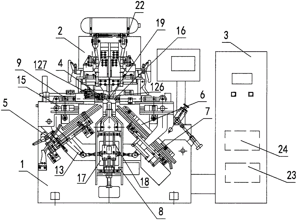
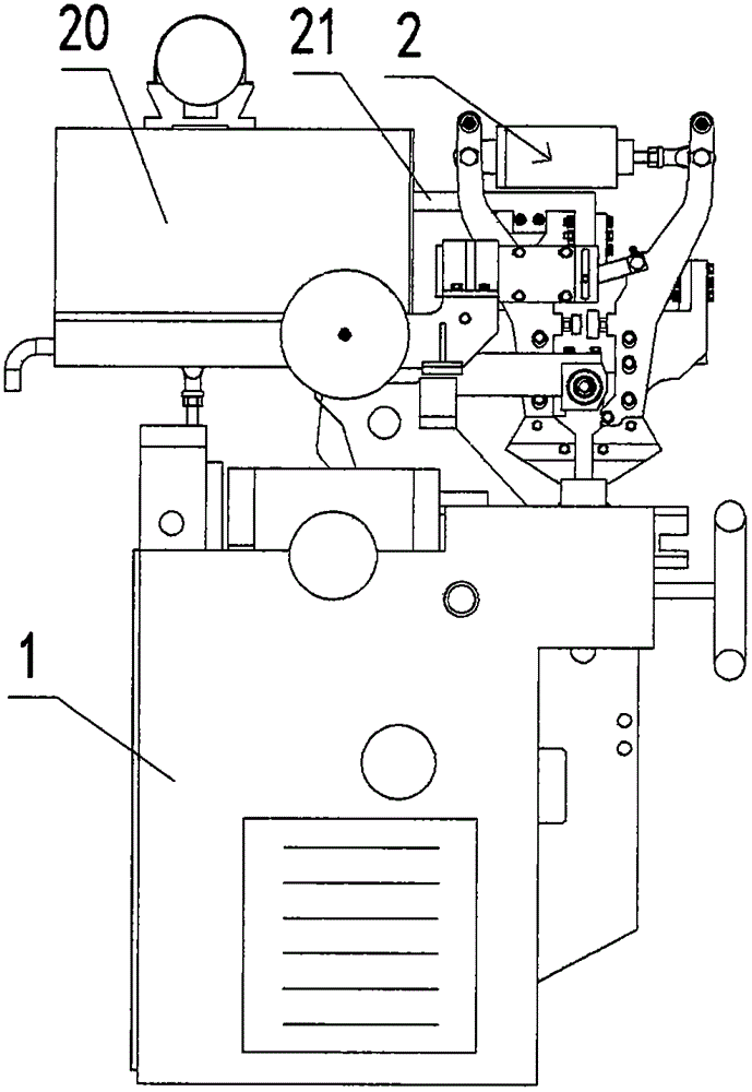
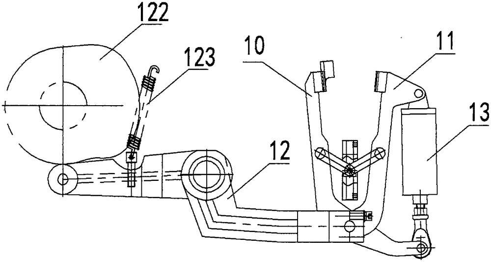
[0022] Such as figure 1 , shown in 2, 3, and 4, the large-diameter circular chain welding machine includes a base 1, and a welding stand 2 is linked by a guide rail above the base, and a welding stand is provided between the welding stand and the base to realize the welding stand up and down. Moving cam set. An electrical control cabinet 3 is provided on one side of the welding platform, a horizontal workbench 4 is provided on the base, and an input track 5 and an output track 6 are respectively arranged on both sides of the horizontal workbench, and the input track and the output track form an included angle of 95°. The included angle can not only reduce the occupied space of the conventional structure, but also enable the workpiece to be in a better processing position when it reaches the horizontal workbench. Through the setting of this angle, it is generally possible to reduce the occupied space by about 20%. The input track and the output track form a 95° equidistant ang...

Embodiment 2

[0025] Such as figure 1, shown in 2, 3, and 4, the large-diameter circular chain welding machine includes a base 1, and a welding stand 2 is linked by a guide rail above the base, and a welding stand is provided between the welding stand and the base to realize the welding stand up and down. Moving cam set. An electrical control cabinet 3 is arranged on one side of the welding platform, a horizontal workbench 4 is arranged on the base, and an input track 5 and an output track 6 are respectively arranged on both sides of the horizontal workbench, and the input track and the output track form an included angle of 99°. The included angle can not only reduce the occupied space of the conventional structure, but also enable the workpiece to be in a better processing position when it reaches the horizontal workbench. Through the setting of this angle, it is generally possible to reduce the occupied space by about 20%. The input track and the output track form a 99° equidistant angl...

Embodiment 3

[0028] Such as figure 1 , shown in 2, 3, and 4, the large-diameter circular chain welding machine includes a base 1, and a welding stand 2 is linked by a guide rail above the base, and a welding stand is provided between the welding stand and the base to realize the welding stand up and down. Moving cam set. An electrical control cabinet 3 is arranged on one side of the welding platform, a horizontal workbench 4 is arranged on the base, and an input track 5 and an output track 6 are respectively arranged on both sides of the horizontal workbench, and the input track and the output track form an included angle of 98°. The included angle can not only reduce the occupied space of the conventional structure, but also enable the workpiece to be in a better processing position when it reaches the horizontal workbench. A mechanical arm 7 capable of pulling the chain to move is provided on the output track, and the mechanical arm mainly plays the role of pulling the chain. The horiz...


PUM

PropertyMeasurementUnit
lengthaaaaaaaaaa
angleaaaaaaaaaa

Abstract

The invention relates to the technical field of machinery, discloses an automatic welding machine and particularly relates to a large-diameter circular ring chain welding machine. The large-diameter circular ring chain welding machine comprises a base. A welding stand is connected to the upper portion of the base through guide rails. A horizontal workbench is arranged on the base. The two sides of the horizontal workbench are provided with an input rail and an output rail respectively. A mechanical arm capable of pulling a chain to move is arranged on the output rail. A positioning clamp set is arranged on the horizontal workbench. A welding point is arranged on the horizontal workbench. A rectifier is arranged on the welding stand. The rectifier is connected with the welding point through a connecting piece. An intermediate-frequency welding transformer is connected to the rectifier. The intermediate-frequency welding transformer is connected with a frequency converter connected with three-phase voltage through a welding inverter. The large-diameter circular ring chain welding machine has the advantages that the original conversion from alternating-current welding to direct-current welding is achieved, and the problem of energy source consumption of 15% attenuation per meter caused by inductive reactance on account of power output is solved.

Description

technical field [0001] The invention relates to the field of mechanical technology, and refers to an automatic welding machine, especially a large-diameter circular chain welding machine. Background technique [0002] Welding ensures the continuity of the metal. On the one hand, the two metals are connected to each other by bolts or physical attachment, which is a strong metal whole, but this connection is discontinuous. Sometimes, if there is an oxide insulating film on the surface of the metal, they even Right or wrong physical contact. Another disadvantage of mechanical connection compared with welding is that the contact surface continues to oxidize, resulting in an increase in resistance. Additionally, vibration and other mechanical shocks can loosen joints. Welding eliminates these problems, the welding part does not move relative to each other, the contact surface will not be oxidized, and the continuous conduction method can be maintained. With the feature of wel...

Claims


Application Information

Patent Timeline
Patent Type & Authority Applications(China)
IPC IPC(8): B23K31/02B23K37/00B23K37/04B23K101/30
CPCB23K31/02B23K37/00B23K37/0435B23K2101/30
Inventor 杨育萃
Owner HANGZHOU XIAOSHAN JIUYUAN MACHINERY
Learn More