Condensing tower

A condensing tower and shell technology, which is applied in the field of condensing towers, can solve the problems of water loss, ineffective heat transfer, and easy blockage of water distribution holes, etc., and achieves reduced drift loss, excellent waterproof effect, and reduced drift loss Effect

Active Publication Date: 2016-02-03
江苏河海新能源技术发展有限公司
View PDF10 Cites 0 Cited by
  • Summary
  • Abstract
  • Description
  • Claims
  • Application Information

AI Technical Summary

Problems solved by technology

[0003] The existing condensing towers have the following disadvantages: the heat exchange effect is not obvious; when the condensing tower is running, water drifting will occur, resulting in water loss, and water needs to be replenished frequently. At the same time, the cooling water wi

Method used


Image

  • Condensing tower
  • Condensing tower
  • Condensing tower

Examples


Embodiment Construction

[0025] The present invention will be further described below in conjunction with the accompanying drawings and specific embodiments.

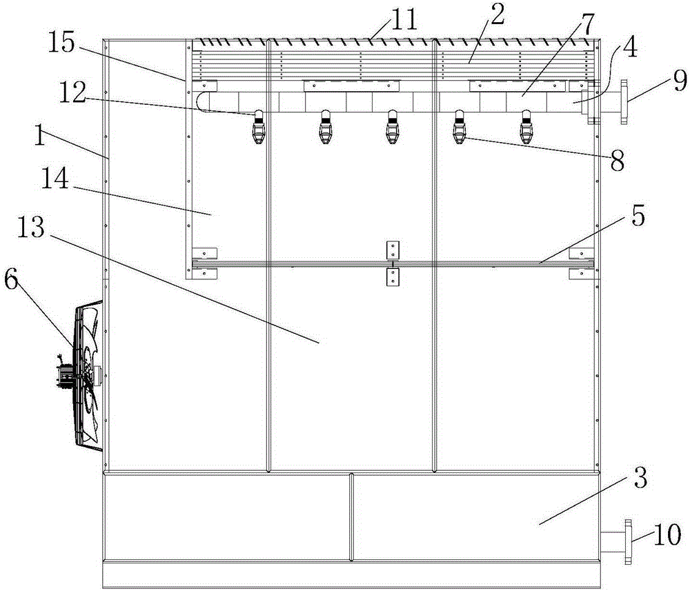
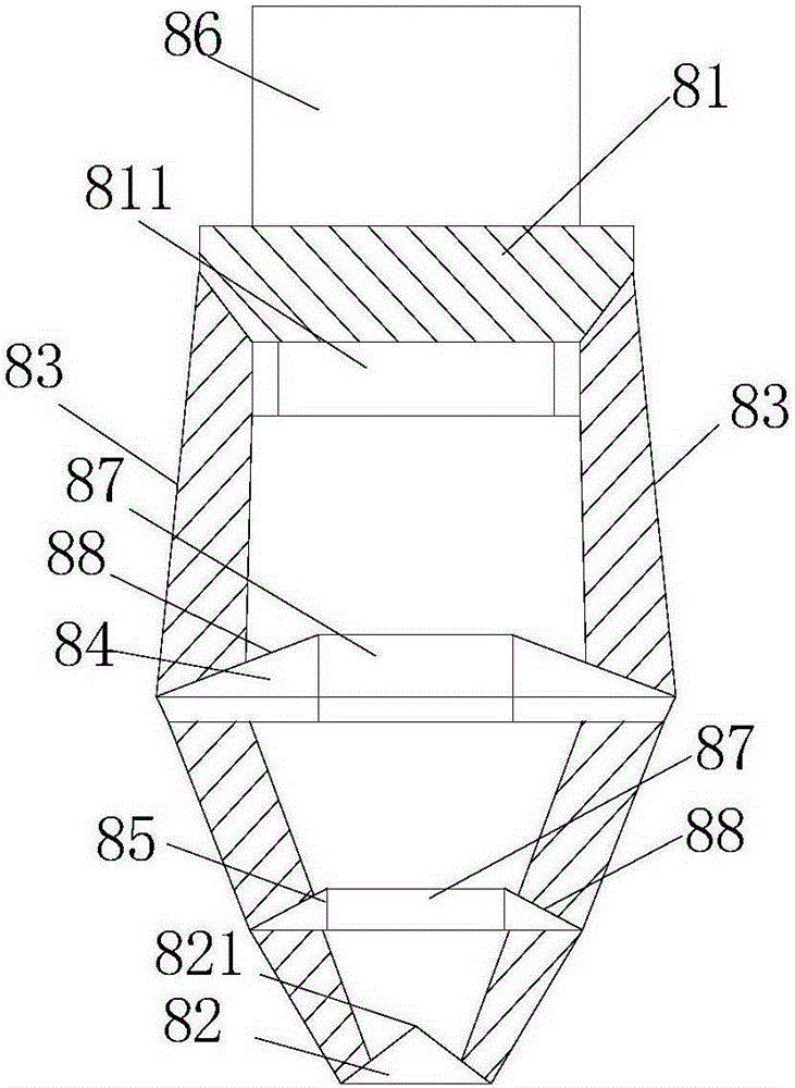
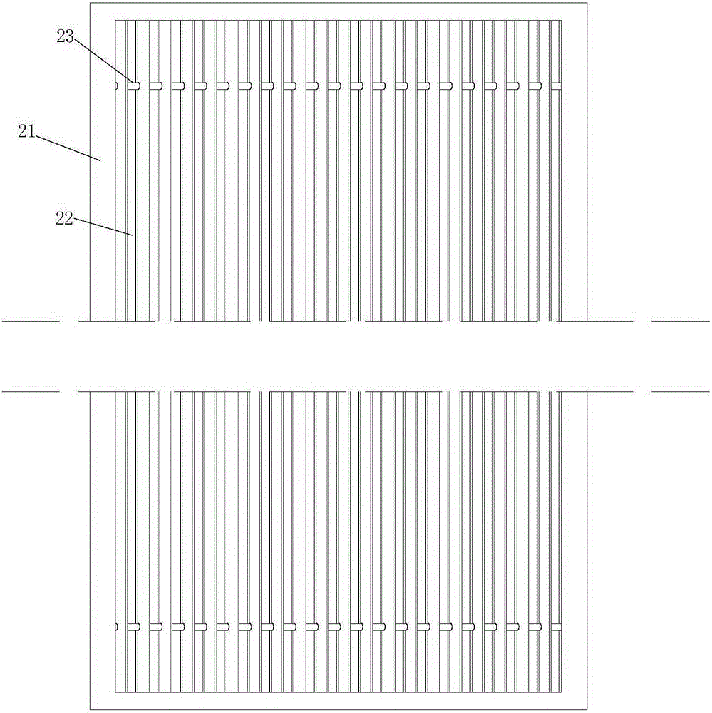
[0026] Such as Figure 1 to Figure 8 , Condensing tower, including housing 1 with inner chamber, blower fan 6, and the clapboard 15 that is arranged inside shell 1, water tank 3, water spraying system 4, honeycomb net device 5 and demister 2, described clapboard One end of 15 is fixedly connected to the upper end of the housing 1, the lower end of the partition 15 is fixedly connected to one end of the honeycomb device 5, the other end of the honeycomb device 5 is connected to the side wall of the housing 1, and the partition 15 is connected to the honeycomb device 5. The inner cavity of the housing 1 is divided into a first cavity 13 and a second cavity 14, the first cavity is the air inlet section, the second cavity is the water spray section, the upper end of the first cavity 13 is a closed structure, and the second cavity is a closed struct...


PUM


Abstract

The invention relates to a condensing tower. The condensing tower comprises a shell with an inner cavity, a draught fan, a partition plate arranged in the shell, a water tank, a water spraying system, a honeycomb net device and a defroster. One end of the partition plate is fixedly connected with the upper end of the shell, and the lower end of the partition plate is fixedly connected with one end of the honeycomb net device. The other end of the honeycomb net device is connected with the side wall of the shell. The inner cavity of the shell is divided into a first cavity and a second cavity through the partition plate and the honeycomb net device. The upper end of the first cavity is of a closed structure. The upper end of the second cavity is of a shutter structure. The water tank is arranged in the first cavity and located at the lower end of the first cavity. The defroster and the water spraying system are arranged in the second cavity and connected with the shell and the partition plate respectively. The defroster is located above the water spraying system. The draught fan is arranged on the side face of the outer side of the shell and located above the water tank and below the honeycomb net device. The draught fan is communicated with the first cavity. The condensing tower has the beneficial effects of being low in water bleaching rate, good in heat exchange effect, capable of saving water, convenient to hoist, and the like.

Description

technical field [0001] The invention relates to the technical field of condensation towers, in particular to a condensation tower. Background technique [0002] The condensing tower is a device that uses water as a circulating coolant to absorb heat from the system and discharge it to the atmosphere to reduce the water temperature; its cooling is to use water and air to exchange heat and cold to generate steam, and the steam volatilizes to take away heat to achieve evaporation and heat dissipation , Convective heat transfer and radiation heat transfer and other principles to dissipate waste heat generated in industry or in refrigeration and air conditioning to reduce the water temperature of the evaporative cooling device to ensure the normal operation of the system. The device is generally barrel-shaped, so it is called a condensation tower. The condensation tower is a comprehensive product integrating aerodynamics, thermodynamics, fluids, chemistry, biochemistry, materials...

Claims


Application Information

Patent Timeline
IPC IPC(8): F28C1/00F28F25/00F28F25/04F28F25/06F28F25/10
Inventor 王超生杨家华荆国政倪建飞
Owner 江苏河海新能源技术发展有限公司
Why Eureka
Try Eureka