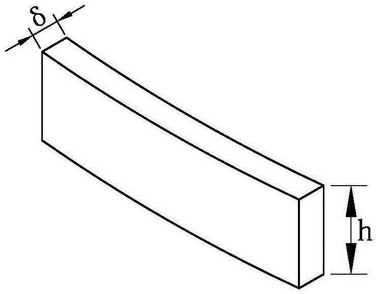
Diamond tool bit parameter measurement device and diamond saw blade welding machine
A technology of diamond cutter heads and diamond saw blades, which is applied in the field of machine tools, can solve problems such as unsatisfactory measurement accuracy, and achieve the effects of simplified structure, strong controllability, and guaranteed measurement accuracy
- Summary
- Abstract
- Description
- Claims
- Application Information
AI Technical Summary
Problems solved by technology
Method used
Image
Examples
Embodiment 1
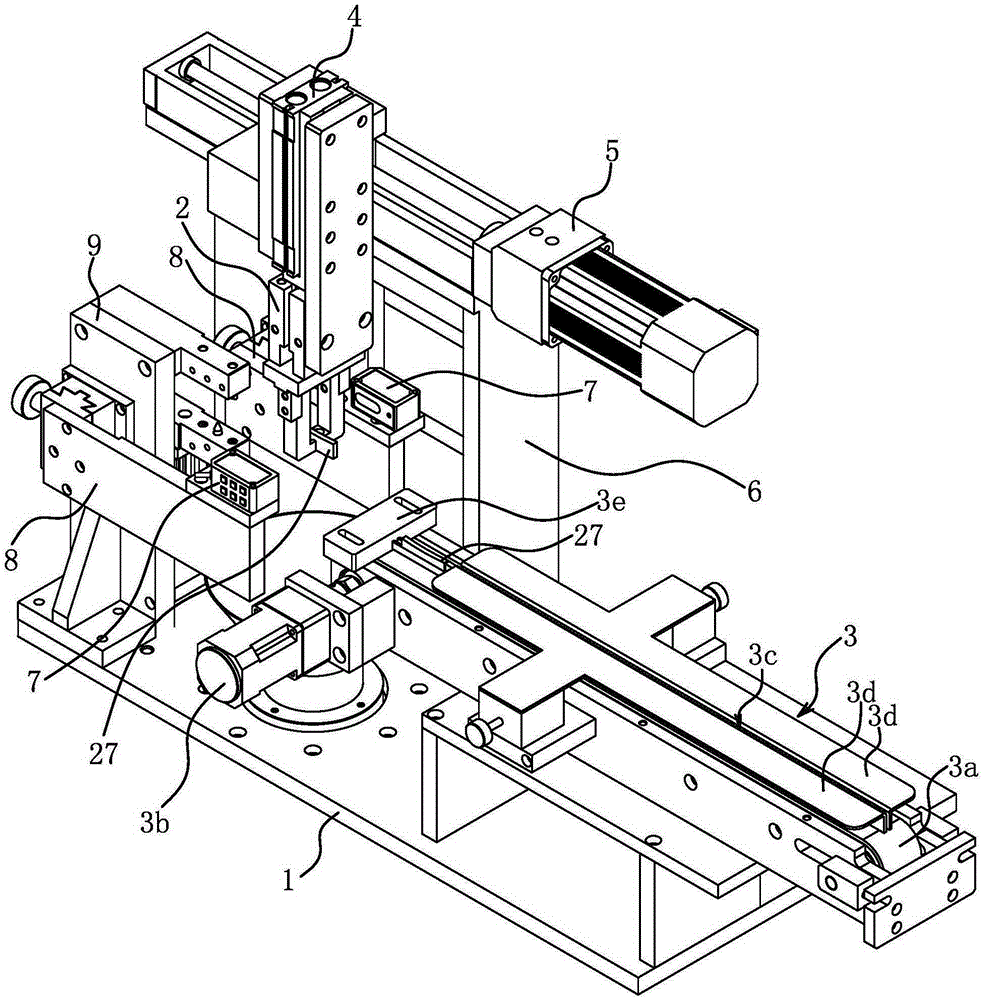
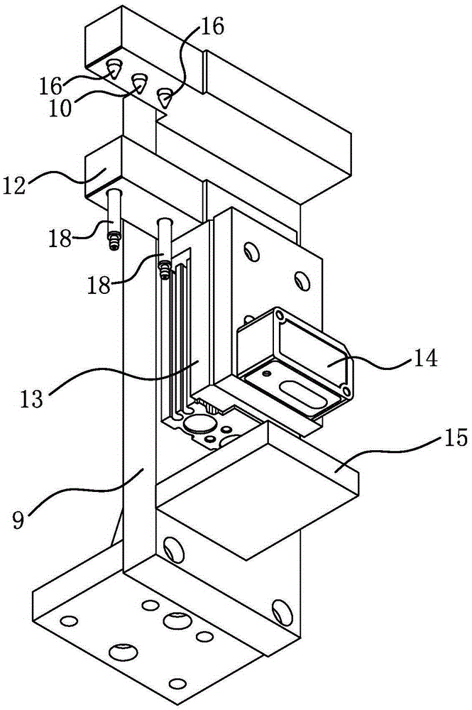
[0024] Such as Figure 2 to Figure 4 As shown, the diamond cutter head parameter measuring device includes a worktable 1, a pneumatic clamp 2, a thickness measuring component and a first control circuit.
[0025] The workbench 1 is a basic part, and the workbench 1 is arranged horizontally.
[0026] The workbench 1 is provided with a conveyor belt 3a assembly 3 capable of horizontally conveying the diamond cutter head 27. The conveyor belt 3a assembly 3 includes a horizontally arranged conveyor belt 3a. Two rotating wheels are arranged in the conveyor belt 3a. The rotary wheel and the workbench The plates 1 are connected in rotation, and a motor 3b is fixed on the worktable 1, and the motor 3b is connected to one of the rotating wheels through transmission. The top of the conveyor belt 3a is provided with a guide plate 3d forming a guide groove 3c and a stopper 3e that prevents the diamond bit 27 from moving; both the stopper 3e and the guide plate 3d are fixed on the worktab...
Embodiment 2
[0041] Such as Figure 5 and Figure 6 As shown, the diamond saw blade welding machine includes a frame 19, a second control circuit, a cutter head clamping device 20, a clamp 21 and a thickness measuring assembly.
[0042] Frame 19 is a base part, and frame 19 is vertically arranged.
[0043] The clamp 21 is used to position the diamond saw blade substrate 28. The clamp 21 includes a base plate 21a. The base plate 21a of the clamp 21 is connected to the frame 19 through a second numerically controlled guide feeding assembly 22. The second numerically controlled guide feed assembly 22 is connected to the first A numerically controlled guide feed assembly 5 has the same structure, so no redundant description is given here. The linear guide rail is vertically arranged in the second numerically controlled guide feeding assembly 22, so that the clamp 21 can be vertically lifted. The numerical control motor in the third numerical control guiding feed component is electrically co...
Embodiment 3
[0049] The structure and principle of this embodiment are basically the same as that of Embodiment 1, and the basic similarities will not be described redundantly. Only the differences will be described. The difference lies in the structure where the sensor mounting plate 23 is installed: as Figure 7 and Figure 8 As shown, the sensor mounting plate 23 is connected to the frame 19 through a height adjustment assembly 25 . The height adjustment assembly 25 includes a fixed plate 25 a and a movable plate 25 b, and the fixed plate 25 a is fixedly connected with the frame 19 . A rotating shaft 26 is fixed on the sensor mounting plate 23, and the rotating shaft 26 penetrates the movable plate 25b and is rotationally connected with the movable plate 25b.
[0050] By the height of the lifting fixture 21 and the rotation of the movable plate 25b, the outer edge of the diamond saw blade substrate 28 positioned on the fixture 21 can be embedded between the two laser distance measuring...
PUM
 Abstract
Description
Claims
Application Information
 - R&D
- Intellectual Property
- Life Sciences
- Materials
- Tech Scout
- Unparalleled Data Quality
- Higher Quality Content
- 60% Fewer Hallucinations
Browse by: Latest US Patents, China's latest patents, Technical Efficacy Thesaurus, Application Domain, Technology Topic, Popular Technical Reports.
© 2025 PatSnap. All rights reserved.Legal|Privacy policy|Modern Slavery Act Transparency Statement|Sitemap|About US| Contact US: help@patsnap.com


