Scanning card

A scanning card and pin technology, applied in the field of scanning cards, can solve problems such as inconvenience of multi-core cables, reduced reliability, abnormal display, etc., and achieve the effect of solving electromagnetic compatibility problems, facilitating production and testing, and convenient installation process.

Active Publication Date: 2016-02-03
XIAN NOVASTAR TECH
View PDF8 Cites 6 Cited by
  • Summary
  • Abstract
  • Description
  • Claims
  • Application Information

AI Technical Summary

Problems solved by technology

[0005] (1) Each single-ended signal needs to occupy one wire core, resulting in a large number of wire cores for wiring. Take a conventional 8-scan LED light board as an example. If you need two sets of RGB data, add CLK, LAT, OE , A, B, C and other control signals have a total of 12 single-ended signals, plus at least one ground signal, at least 13-core cable is required; however, there are often some applications in the LED display industry that have limited access to cable The number of wire cores is limited, and multi-core wiring is inconvenient
[0006] (2) Due to the large number of cable cores, there are also many contact points between the cable and the connector between the LED ligh

Method used


Image

  • Scanning card
  • Scanning card
  • Scanning card

Examples


Embodiment Construction

[0028] In order to make the above objects, features and advantages of the present invention more comprehensible, specific implementations of the present invention will be described in detail below in conjunction with the accompanying drawings.

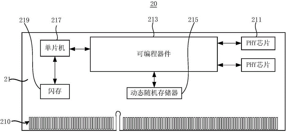
[0029] See figure 2 A scanning card 20 proposed by the present invention includes: a circuit board 21 and a golden finger interface 210 arranged on the circuit board 21, a PHY chip (that is, a physical layer transceiver chip) 211, a programmable device 213, and a dynamic random access memory 215 , single-chip microcomputer 217 and flash memory 219.

[0030] The golden finger interface 210 is located on one side of the circuit board 21 and includes a plurality of pins distributed on two opposite surfaces of the side. In this embodiment, the gold finger interface 210 has 204 pins, so 102 pins are respectively provided on two opposite surfaces of the side of the circuit board 21 . In addition, in a preferred embodiment, the length of t...


PUM


Abstract

The invention relates to a scanning card. The scanning card comprises a circuit board, a programmable device and a PHY chip, wherein the programmable device and the PHY chip are arranged on the circuit board and the PHY chip is electrically connected with the programmable device. The scanning card also comprises gold finger ports arranged on one side edge of the circuit board. The gold finger port comprises a network port pin group, an RGB data output pin group and a display control signal output pin group. The network port pin group is electrically connected with the PHY chip. The RGB data output pin group and the display control signal output pin group are electrically connected with the programmable device. Thus, the gold finger ports are arranged in the scanning card and corresponding inserting grooves are arranged in an LED lamp plate, so when the LED lamp plate is lightened, RGB data and control signals between the scanning card and the LED lamp plate can be transported completely without the former redundant wiring but the more convenient PCB wiring on the LED lamp plate. In addition, all pins on the gold finger ports are defined, thereby facilitating production test, user installation and post maintenance.

Description

technical field [0001] The invention relates to the technical field of LED display control, in particular to a scanning card. Background technique [0002] In the existing LED display synchronous control system, the video source sends the video signal to the sending card through the video interface, and then the sending card is responsible for converting the video signal into a digital signal and distributing the digital signal, outputting it from multiple output interfaces to Receiving cards in different LED boxes connected to it. Since the receiving card itself stores the parameters of the LED box where it is located, after the scanning card receives the display data, it will reverse the received data according to the wiring mode of the light board driver chip it carries, and then transfer the data Passed to the data input terminal of the light board driver chip. While receiving the image data, the light board driver chip will also receive the control signal sent by the ...

Claims


Application Information

Patent Timeline
IPC IPC(8): G09G3/36G09G3/34
Inventor 梁伟王伙荣袁胜春
Owner XIAN NOVASTAR TECH
Why Eureka
Try Eureka