Production method of wireless charge coil and wireless charge coil

A technology of wireless charging and manufacturing method, which is applied in coil manufacturing, battery circuit devices, circuits, etc., which can solve problems such as coils cannot be accommodated, coils are easy to fall apart, and coil shapes cannot be designed, so as to achieve the effect of not being easily deformed

Active Publication Date: 2016-02-03
SHANGHAI AMPHENOL AIRWAVE COMM ELECTRONICS CO LTD
View PDF4 Cites 11 Cited by
  • Summary
  • Abstract
  • Description
  • Claims
  • Application Information

AI Technical Summary

Problems solved by technology

[0004] 1. Since the cross-section of the enameled wire winding coil is circular, the cross-sectional area can only be increased by increasing the diameter of the cross-section, and the cross-sectional shape cannot be adjusted according to the actual thickness space that the electronic product can accommodate;
[0005] 2. The winding process can only wind coils with regular shapes such as circular, square and elliptical (limited by the winding process and manufacturing process), and the shape of the coil cannot be designed according to the spatial shape and environment of different products;
[0006] 3. For the coil wound with enameled wire, the flatness error of the entire coil is relatively large, and the error is even greater than 1.5 times the wire diameter. That is to say, if the thickness space of the electronic product is Then only choose The wire diameter of the coil, otherwise the product will not accommodate the coil;
[0007] 4. The coil is easy to fall apart;
[0008] 5. The surface layer of enameled wire needs to occupy a certain thickness of space, which is not conducive to product miniaturization

Method used


Image

  • Production method of wireless charge coil and wireless charge coil
  • Production method of wireless charge coil and wireless charge coil
  • Production method of wireless charge coil and wireless charge coil

Examples


Embodiment Construction

[0036] In order to make the above objects, features and advantages of the present invention more comprehensible, specific implementations of the present invention will be described in detail below in conjunction with the accompanying drawings.

[0037] In the following description, numerous specific details are set forth in order to provide a thorough understanding of the present invention. However, the present invention can be implemented in many other ways different from those described here, and those skilled in the art can make similar extensions without violating the connotation of the present invention, so the present invention is not limited by the specific implementations disclosed below.

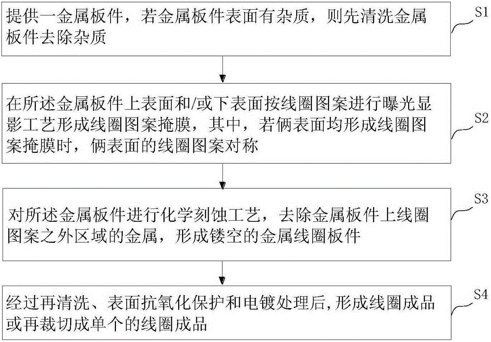
[0038] image 3 A method for manufacturing a wireless charging coil is shown, including the following steps:

[0039] S1: Provide a metal plate, if there are impurities on the surface of the metal plate, first clean the metal plate to remove impurities;

[0040] S2: Exposing and d...


PUM

PropertyMeasurementUnit
thicknessaaaaaaaaaa
thicknessaaaaaaaaaa
thicknessaaaaaaaaaa

Abstract

The invention provides a production method of a wireless charge coil and a wireless charge coil. The production method comprises the following steps: S1, providing a metal plate, and first washing the metal plate to remove impurities if the surface of the metal plate has impurities; S2, carrying out the exposure developing process on the upper surface and/or the lower surface of the metal plate according to a coil design pattern to form a coil pattern mask, wherein if the coil pattern mask is formed on both surfaces, the coil patterns on the two surfaces are symmetric; S3, chemically etching the metal plate, removing metal in the area outside the coil pattern on the metal plate, and forming a hollowed metal coil plate; S4, re-washing the metal plate, carrying out the surface anti-oxidation protection and electroplating protection treatment on the metal plate to form a coil finished product, or re-cutting to form a single coil finished product. The production method can be used in a product environment with limited thickness space, can produce the shape of the coil according to different spatial shape requirements and is high in charge efficiency.

Description

technical field [0001] The invention belongs to the coil technology, and in particular relates to a coil with a planar structure, such as a coil for wireless charging technology. Background technique [0002] Inductive charging coil or non-contact charging coil is a new charging technology derived from wireless power transmission technology. It can be used for short-distance non-contact wireless charging devices that use the principle of near-field induction conduction to transmit energy. Charge mobile communication devices, PC (personal computer) devices, small smart electronic products, smart wearable products, etc. [0003] For coils used in mobile communication equipment, PC equipment and wireless charging devices for small smart electronic products, the inductance value of the coil is required to be above 12uH, the DC impedance value of the total length of the coil is required to be less than 1ohm, and the efficiency of the entire charging system is required to be great...

Claims


Application Information

Patent Timeline
Patent Type & Authority Applications(China)
IPC IPC(8): H01F41/04H01F38/14H02J50/10H02J7/00
Inventor 蒋海英唐磊邹继鸿
Owner SHANGHAI AMPHENOL AIRWAVE COMM ELECTRONICS CO LTD
Why Eureka
Try Eureka