
Microstrip antenna capable of electrical adjustment of beam direction and beam width

A technology of beam direction and beam width, which is applied in the field of reconfigurable microstrip antennas, can solve the problems of antenna complex feeding network, etc., and achieve the effect of simple feeding network, wide application range and easy processing

Pending Publication Date: 2016-02-03
JIANGSU ELECTRIC POWER CO +1
View PDF0 Cites 10 Cited by
  • Summary
  • Abstract
  • Description
  • Claims
  • Application Information

AI Technical Summary

Problems solved by technology

[0004] There are many ways to electrically adjust the beam direction. The most common method is to use a phased array to feed currents of different phases to the elements of the antenna to adjust the beam direction. However, this method requires a complex feed network for antennas with many elements.

Method used


Image

  • Microstrip antenna capable of electrical adjustment of beam direction and beam width
  • Microstrip antenna capable of electrical adjustment of beam direction and beam width
  • Microstrip antenna capable of electrical adjustment of beam direction and beam width

Examples


Embodiment 1

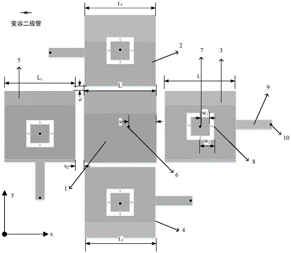
[0027] Example 1 as figure 1 As shown, a microstrip antenna with electrically adjustable beam direction and beam width includes a dielectric plate, a radiation patch distributed on the same surface of the dielectric plate, and a ground plate distributed on the other side of the dielectric plate. The radiation patch It includes a square drive patch and four square parasitic patches of the same size. The four parasitic patches are distributed around the four sides of the drive patch. Any parasitic patch is parallel to the adjacent side of the drive patch. There is an endless slit on the patch, preferably, the slit is square, the part of the parasitic patch surrounded by the slit is defined as the positive area of ​​the parasitic patch, and the part of the parasitic patch outside the slit defines is the negative area of ​​the parasitic patch, the positive area is electrically connected to the negative area through a varactor diode, and the periphery of the negative area of ​​the ...


PUM


Abstract

The invention discloses a microstrip antenna capable of electrical adjustment of beam direction and beam width. The antenna mainly comprises three parts: five microstrip radiation patch units, a substrate, and a feeding circuit, continuous adjustment of the beam direction and the beam width in two vertical planes xoz and yoz can be realized via the adjustment of the control voltage of a varactor, the adjustable range of the beam direction is -20 degrees to 20 degrees, and the adjustable range of the beam bandwidth is 90 degrees to 120 degrees. The microstrip Yagi-Uda antenna capable of electrical adjustment of beam direction and beam width is advantageous in that at the working frequency point, the feeding circuit is simple, the echo loss is low, the gain variation range is small, and the cross polarization discrimination rate is high.

Description

technical field [0001] The present invention relates to the technical field of antennas, in particular to a reconfigurable microstrip antenna whose beam direction and beam width can be adjusted by voltage with broad application prospects. Background technique [0002] As a device for sending and receiving information in a communication system, the antenna plays an important role in the communication system. The base station antenna is the application of the antenna in the cellular mobile communication network, and it has special requirements on the radiation characteristics of the antenna. In power wireless communication systems, macro-area coverage is generally used, and most users are in a static state, and the non-uniform regional distribution characteristics of users and business requirements are more prominent, and this non-uniform characteristic exists for a long time, so it is difficult to locate hot spots Users in a cell or sector are scheduled to other cells or sec...

Claims


Application Information

Patent Timeline
Patent Type & Authority Applications(China)
IPC IPC(8): H01Q1/38H01Q1/50H01Q3/26H01Q3/28
Inventor 韦磊陆忞王杰李维刘少君
Owner JIANGSU ELECTRIC POWER CO
Learn More