Motor and rotor power device, aircraft

A power output and stator technology, which is applied in aircraft, electromechanical devices, rotorcraft, etc., can solve the problems of unbalanced force on the output shaft of the motor, easy overload and heat generation of the rotor, and affect the performance of the machine, so as to improve the driving torque and the rotation process. Stable and efficient, uniform load and force effect

Active Publication Date: 2016-02-03
ZHUHAI PANLEI INTELLIGENT TECH CO LTD
View PDF7 Cites 2 Cited by
  • Summary
  • Abstract
  • Description
  • Claims
  • Application Information

AI Technical Summary

Problems solved by technology

However, the force output end of this type of motor bears external force in a unilateral way, and the force on the output shaft of the motor is unbalanced and subjected to a large flexural moment, especially for some more sophisticated machines such as aircraft. , this unbalanced force tends to affect

Method used


Image

  • Motor and rotor power device, aircraft
  • Motor and rotor power device, aircraft
  • Motor and rotor power device, aircraft

Examples


no. 1 example

[0046] Such as Figure 12 As shown, the quadcopter of this embodiment presents a cross shape, and blades 91 and a motor 92 are installed at the end of the cross arm 90. The motor 92 is the rotor power device described in the above rotor power device embodiment, and will not be repeated here. .

no. 2 example

[0048] Such as Figure 13 As shown, the quadcopter of this embodiment presents an I-shaped shape, and the aircraft includes a frame 93 , a first arm 94 and a second arm 95 arranged in parallel. Both ends of the first machine arm 94 and the second machine arm 95 are respectively provided with paddles 96 and a motor 97, the motor 97 has been described in detail in the motor embodiment, and will not be repeated here. The second machine arm 95 is connected to the frame 93 through a rotating shaft 99 , and the second machine arm 95 can rotate relative to the frame 93 .


PUM


Abstract

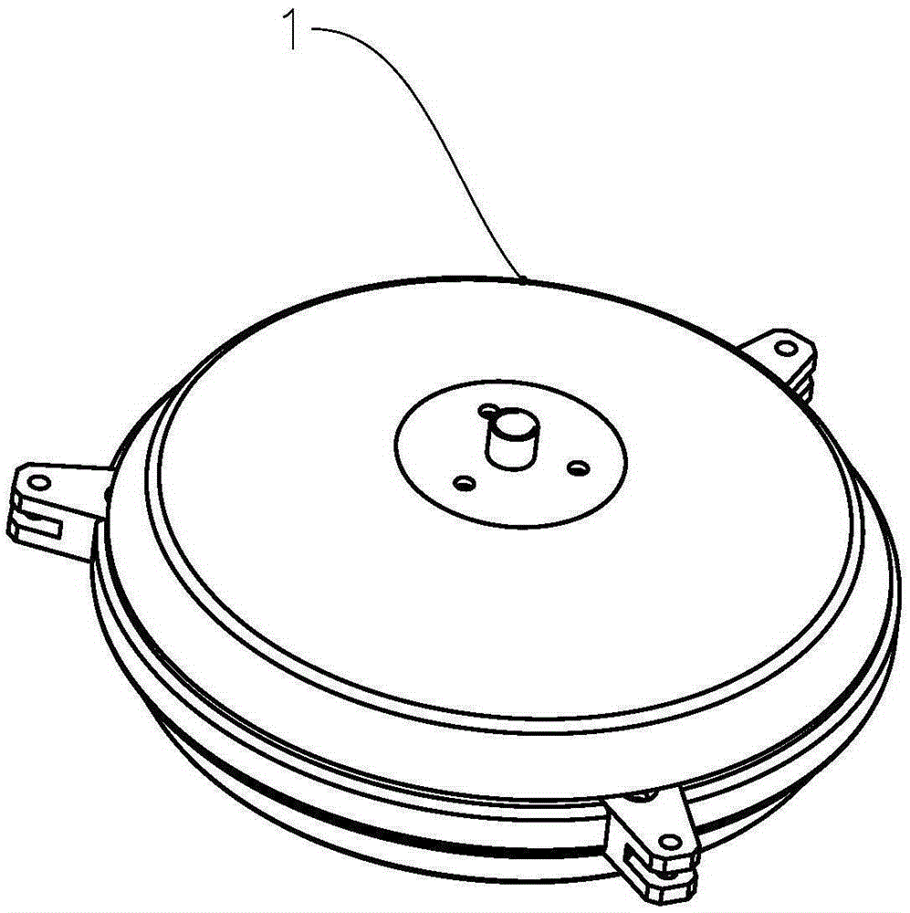
The invention relates to a motor, a rotor power device and an aircraft. The motor includes a rotor, stators and a fixing shaft; the rotor and the stators are distributed with the fixing shaft adopted as an axis; the stators include a first stator and a second stator; the rotor is arranged between the first stator and the second stator; power output interfaces are arranged at the periphery of the rotor; when the rotor rotates around the circumferential direction of the fixing shaft, since driving radius is larger, generated driving torque is larger, and load capacity is increased accordingly; the power output interfaces are located in between the first stator and the second stator, so that stability in rotation can be improved; and a plurality of external components such as blades, which require driving, can be symmetrically arranged along the circumferential direction of the rotor, so that the load and stress of the rotor tend to be more uniform.

Description

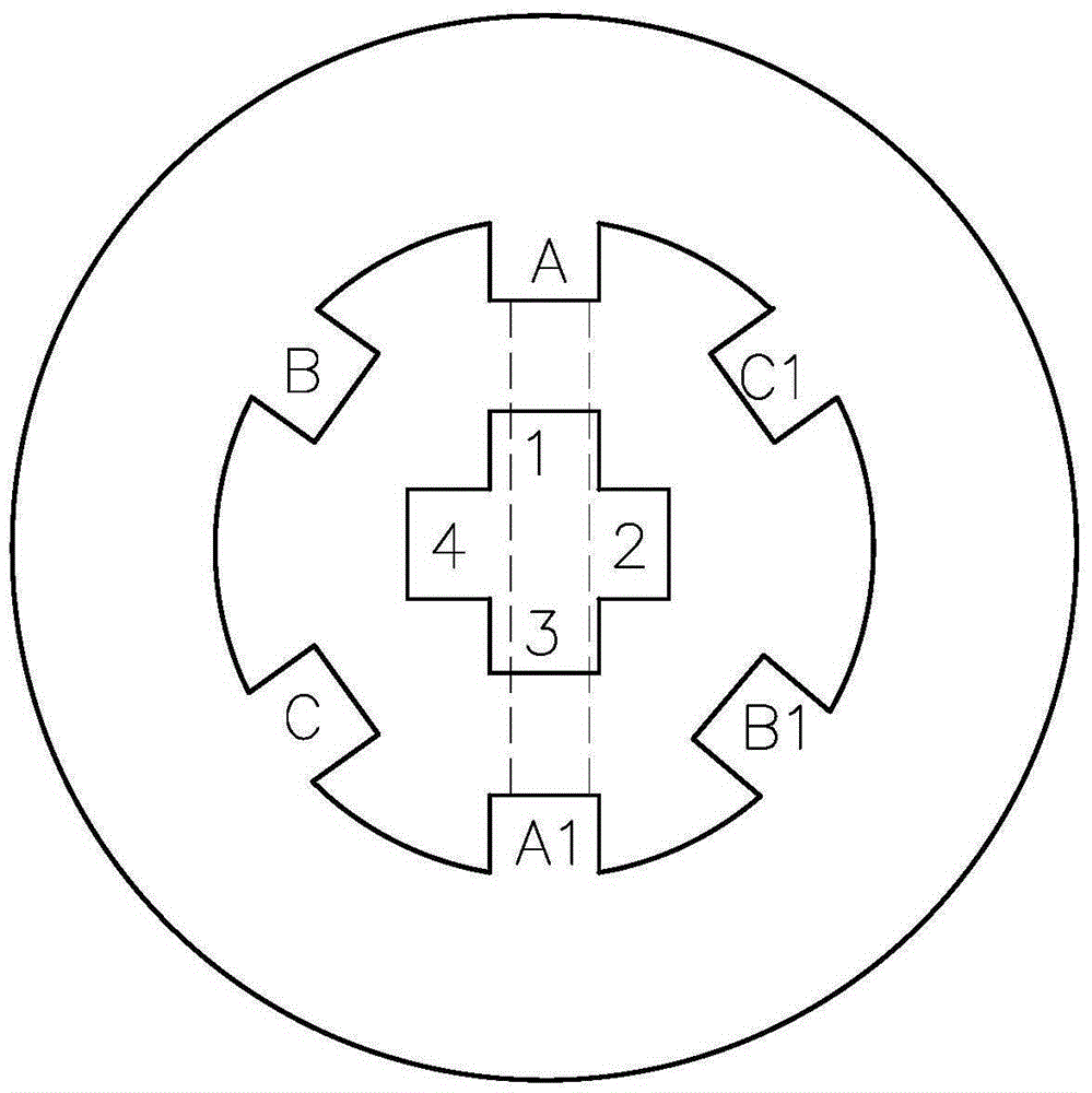
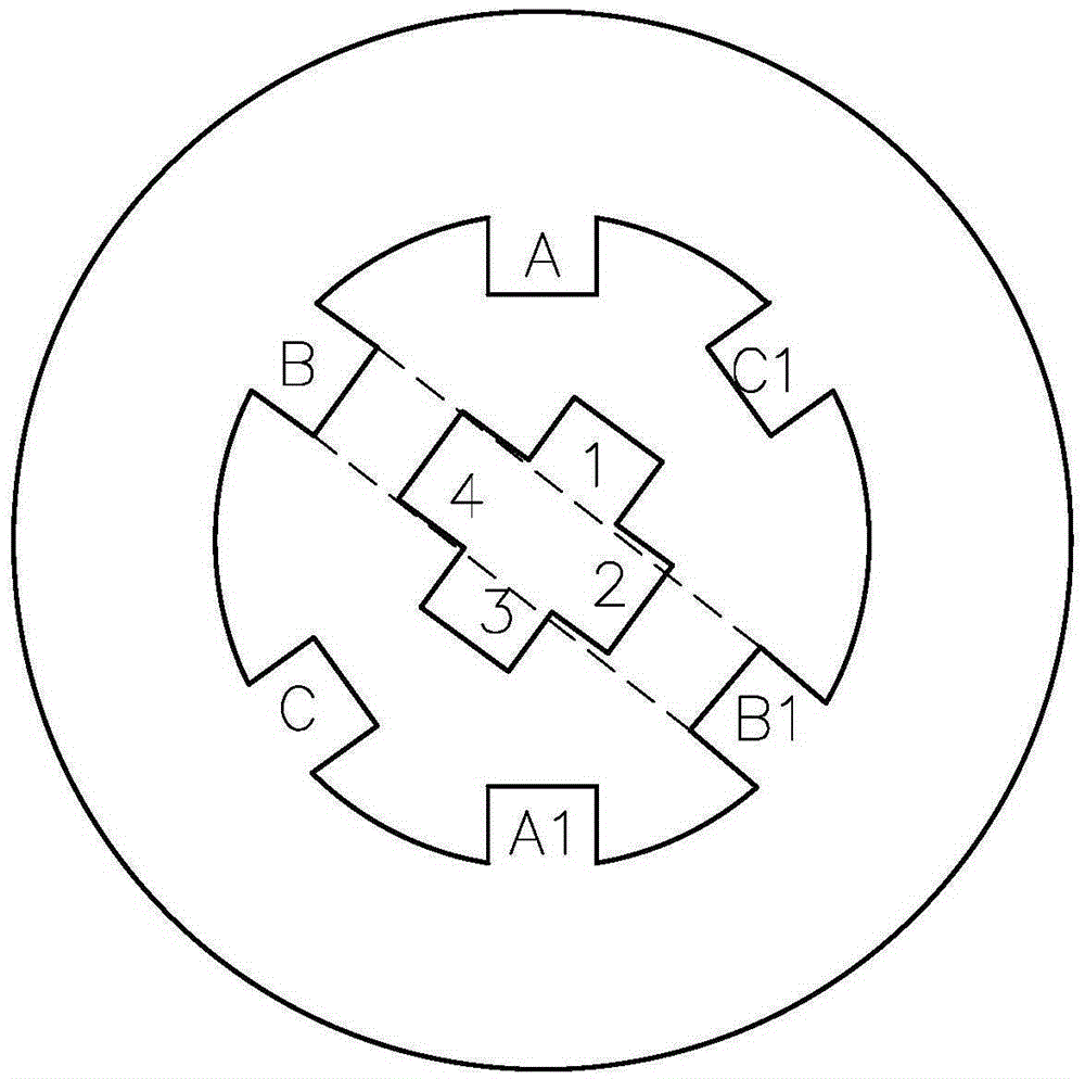
technical field [0001] The invention relates to a motor, a rotor power device and an aircraft using the motor. Background technique [0002] Motor, commonly known as "motor", refers to an electromagnetic device that realizes the conversion or transmission of electric energy according to the law of electromagnetic induction. Its main function is to generate driving torque as a power source for electrical appliances or various machinery. [0003] A stepper motor is a control motor that converts electrical pulse signals into mechanical angular displacements, and is often used as an actuator in a digital control system. A stepper motor mainly includes two parts: a stator and a rotor. Such as figure 1 and figure 2 Shown is a schematic diagram of the structure of a three-phase stepper motor. Such as figure 1 As shown, when phase A is energized, the magnetic flux in the direction of AA1 passes through the rotor to form a closed loop. Generally, the rotor has a certain angle ...

Claims


Application Information

Patent Timeline
IPC IPC(8): H02K16/04B64C27/12
Inventor 何春旺
Owner ZHUHAI PANLEI INTELLIGENT TECH CO LTD
Why Eureka
Try Eureka