
Digital PLL (Phase-Locked Loop) based phase noise measuring device and method

A digital phase-locked loop and phase noise technology, applied in the automatic control of power, electrical components, etc., can solve the problems of affecting the sensitivity of near-end measurement, certain requirements for input power, and no gain adjustment link, etc., to expand the measurement power range , Improve the sensitivity of phase noise measurement, and the effect of good promotion value

Active Publication Date: 2016-02-03
THE 41ST INST OF CHINA ELECTRONICS TECH GRP
View PDF6 Cites 32 Cited by
  • Summary
  • Abstract
  • Description
  • Claims
  • Application Information

AI Technical Summary

Problems solved by technology

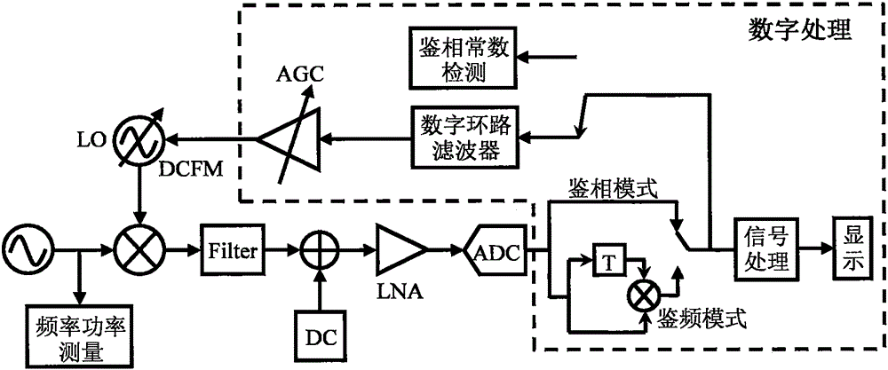
[0014] However, the technical solution adopted by E5052B also needs to be further improved. The loop is very sensitive to the DC component existing in the circuit. DC will not only affect the quadrature phase detection, but also cause ADC saturation, resulting in measurement errors; there is no gain in the loop. In the adjustment link, there are certain requirements for the input power of the source under test, and the power range is narrow; the low gain of the near-end affects the measurement sensitivity of the near-end in the closed loop, and different sources under test have different requirements for the phase noise measurement sensitivity of the near-end and far-end. Targeted optimization of the phase-locked loop is required, and these are also places where the E5052 solution needs to be further optimized

Method used


Image

  • Digital PLL (Phase-Locked Loop) based phase noise measuring device and method
  • Digital PLL (Phase-Locked Loop) based phase noise measuring device and method
  • Digital PLL (Phase-Locked Loop) based phase noise measuring device and method

Examples


specific Embodiment approach

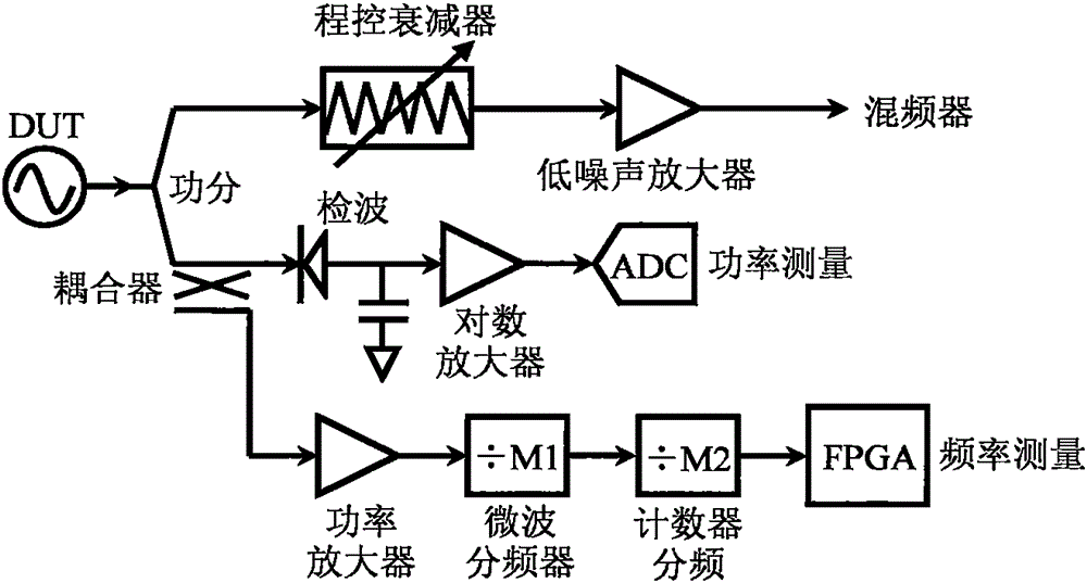
[0092] Such as image 3 As shown, the input signal power of the source under test is divided into two paths: one path is sent to the phase noise measurement part after power adjustment by the program-controlled attenuator, and the other path completes the frequency and power measurement of the source under test. In the frequency power measurement part, the input signal is coupled into two paths by a coupler, and the through signal is sent to AD for acquisition after being subjected to RMS detection, low-pass filtering and logarithmic amplification. The AD measurement voltage and the measured source power approximately satisfy a linear relationship, which can be expressed for:

[0093] P DUT =k×V+P 0

[0094] P DUT Indicates the power of the source under test, P 0 Indicates the compensation value introduced by power division, coupling, etc., k indicates the logarithmic linear coefficient between the detection voltage and power, and the corresponding relationship is determi...


PUM


Abstract

The invention provides a digital PLL (Phase-Locked Loop) based phase noise measuring device. The digital PLL based phase noise measuring device comprises a frequency power measuring unit, a phase discrimination unit, a filtering unit, a DC (Direct Current) bias compensation unit, a low-noise amplification unit, an acquisition, frequency discrimination and phase discrimination unit, a digital loop filtering unit, a phase discrimination constant detection unit, a self-adaptive digital gain control unit, a reference source unit, and a signal processing and displaying unit. According to the digital PLL based phase noise measuring device, a double-balanced mixer is adopted as a phase discriminator, the phase noise of a measured source is extracted through a digital PLL, the specific noise extraction mode is divided into frequency mixer phase discrimination and digital delay line frequency discrimination, and DC caused by a loop circuit is counteracted through a DC bias compensation circuit, so that too big DC after amplification, induced ADC saturation and induced loop lock-losing are prevented. The implementation scheme of the digital PLL based phase noise measuring device is simple, totally excellent phase noise measuring sensitivity can be realized, the realized analysis frequency spectrum range is also very wide, and phase noise testing demands of most signal sources can be satisfied.

Description

technical field [0001] The present invention relates to the technical field of testing, in particular to a phase noise measurement device based on a digital phase-locked loop, and also to a phase noise measurement method based on a digital phase-locked loop, which is used to solve the problems of crystal oscillators, DDS, VCO, YTO, High-sensitivity, wide-range measurement range phase noise test problems for signal sources such as DRO, surface acoustic oscillator, and frequency synthesizer, to meet the phase noise test requirements of signal sources in various electronic devices. Background technique [0002] Phase noise is one of the most important indicators to measure the short-term frequency stability of a signal source. For the phase noise test of signal sources such as crystal oscillators, DDS, VCO, YTO, DRO, surface acoustic oscillators and frequency synthesizers, it is used in aerospace, It plays a very important role in the application of national defense and communi...

Claims


Application Information

Patent Timeline
Patent Type & Authority Applications(China)
IPC IPC(8): H03L7/18
Inventor 朱伟杜念文张士峰李伟刘强
Owner THE 41ST INST OF CHINA ELECTRONICS TECH GRP
Learn More