Steel strip uncoiler

A technology for uncoilers and steel strips, applied in safety equipment, metal processing equipment, manufacturing tools, etc., can solve problems such as high labor intensity, and achieve the effects of reduced labor intensity, simple structure, and reliable work

Active Publication Date: 2016-02-10
NANJING BANKNOTE MINTING +1
View PDF6 Cites 16 Cited by
  • Summary
  • Abstract
  • Description
  • Claims
  • Application Information

AI Technical Summary

Problems solved by technology

[0003] The technical problem to be solved by the present invention is: in order to solve the problem of high labor intensity when threading the steel strip wit

Method used


Image

  • Steel strip uncoiler
  • Steel strip uncoiler
  • Steel strip uncoiler

Examples


Embodiment Construction

[0021] The present invention is described in further detail now in conjunction with accompanying drawing. These drawings are all simplified schematic diagrams, which only illustrate the basic structure of the present invention in a schematic manner, so they only show the configurations related to the present invention.

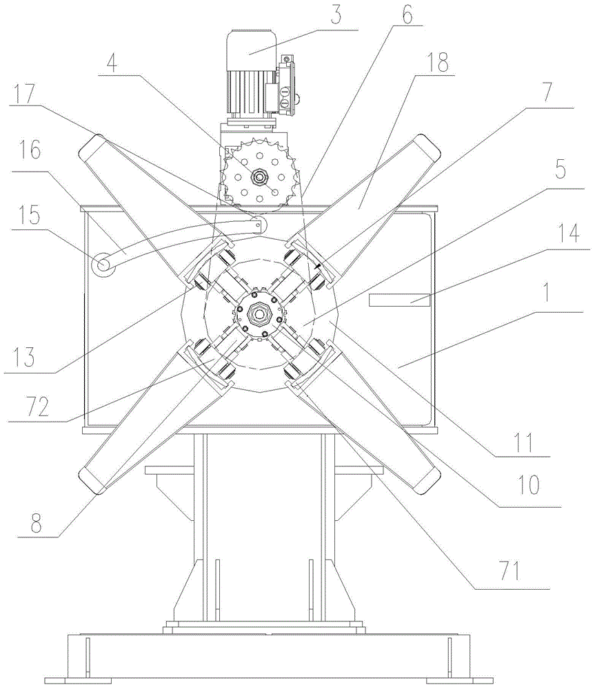
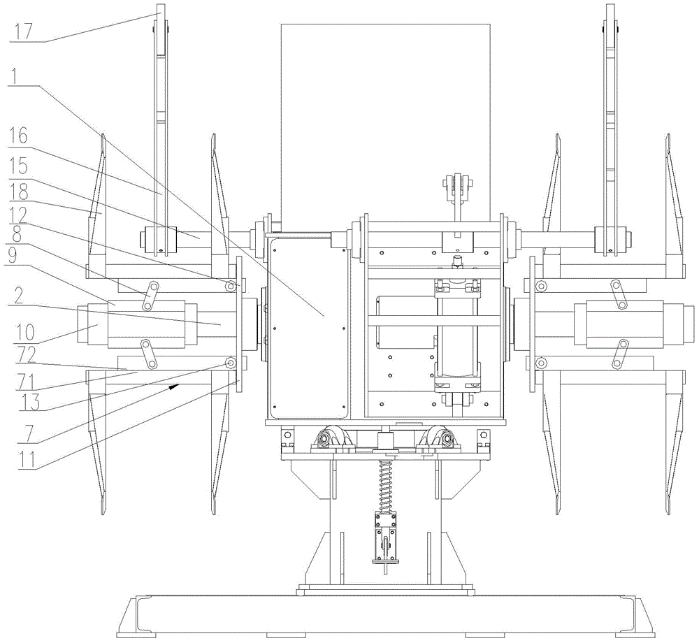
[0022] Such as Figure 1-2 As shown, a kind of strip uncoiler of the present invention comprises uncoil frame, is installed on the uncoil frame 1 and can freely rotate on the uncoil frame 1 center shaft 2 and the power input device that controls center shaft 2 to rotate, so Said central shaft 2 is provided with a supporting body circumferentially on one side away from the unwinding frame 1. The power input device includes a power device and a transmission device. The power device includes a drive motor 3 and a reduction device. The transmission device includes a first sprocket 4, a second Two sprockets 5 and chains 6, the output shaft of the drive motor 3 is ...


PUM


Abstract

The invention relates to a steel strip uncoiler. The steel strip uncoiler comprises an uncoiler rack, a center shaft arranged on the uncoiler rack and freely rotating on the uncoiler rack, and a power input device for controlling the center shaft to rotate, and the circumference of one side of the center shaft far from the uncoiler rack is provided with a supporting body. The steel strip uncoiler has the advantages of simple structure, stable and reliable running and no maintenance on the premise of guaranteeing the constant steel strip uncoiling tension; and additionally, when manual traversing of a steel strip is carried out, a motor is controlled to rotate forward or inversely to drive the center shaft to rotate, so the steel strip on the center shaft moves forward or backward, thereby the labor intensity of an operating personnel is greatly reduced through substituting manual pulling of the steel strip.

Description

technical field [0001] The invention relates to an uncoiling mechanism, in particular to a steel strip uncoiling machine. Background technique [0002] The tension control device of the existing punch steel strip uncoiling mainly consists of a mandrel, a PLC (programmable logic controller), a pneumatic solenoid valve, and a friction plate. When working, the PLC outputs signals to control the pneumatic solenoid valve and the friction plate. Through friction between the friction plate and the mandrel, the purpose of steel strip tension control is finally achieved. Although it can also meet the production requirements, the friction plate and the mandrel are always in friction due to the non-stop production of the equipment for 16 hours. The friction plate must be replaced or adjusted frequently, which affects the production efficiency. In addition, in the manual working mode, there is no motor to drag the steel belt, and the steel belt is completely driven by manpower, which i...

Claims


Application Information

Patent Timeline
IPC IPC(8): B21C47/18B21D55/00
Inventor 李田科汤建华郑军海
Owner NANJING BANKNOTE MINTING
Why Eureka
Try Eureka