Strip uncoiler

A technology for uncoilers and steel strips, applied in safety equipment, metal processing equipment, manufacturing tools, etc., can solve problems such as high labor intensity, achieve the effects of reducing labor intensity, stable operation, and eliminating interference

Active Publication Date: 2017-10-20
NANJING BANKNOTE MINTING +1
View PDF6 Cites 5 Cited by
  • Summary
  • Abstract
  • Description
  • Claims
  • Application Information

AI Technical Summary

Problems solved by technology

[0003] The technical problem to be solved by the present invention is: in order to solve the problem of high labor intensity when threading the steel strip without motor drag under the control of the existing PLC in the manual work mode, the present invention provides a steel strip uncoiler to solve the above problems

Method used


Image

  • Strip uncoiler
  • Strip uncoiler
  • Strip uncoiler

Examples


Embodiment Construction

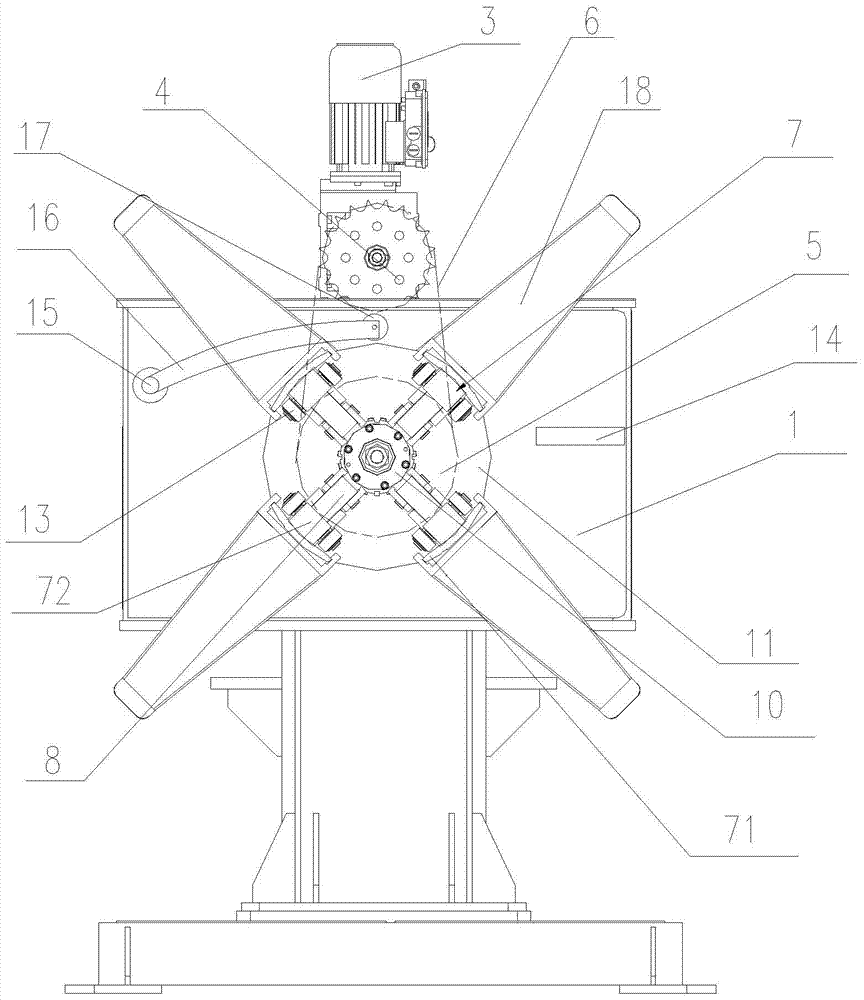
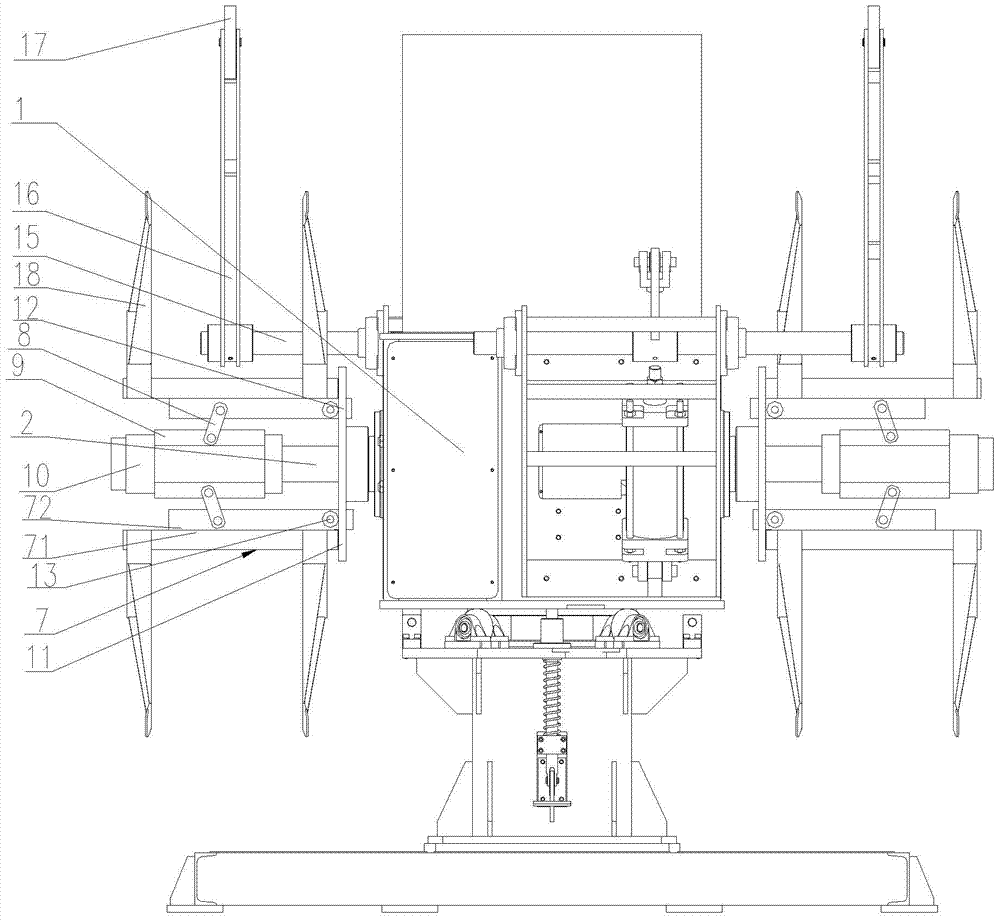
[0021] The present invention will now be described in further detail with reference to the drawings. These drawings are all simplified schematic diagrams, which merely illustrate the basic structure of the present invention in a schematic manner, so they only show the structures related to the present invention.

[0022] Such as Figure 1-2 As shown, a steel belt uncoiler of the present invention includes an uncoiler, a central shaft 2 installed on the uncoiler 1 and freely rotatable on the uncoiler 1, and a power input device that controls the rotation of the central shaft 2, so The central shaft 2 is provided with a support in the circumferential direction on the side far away from the roll frame 1. The power input device includes a power device and a transmission device. The power device includes a drive motor 3 and a deceleration device. The transmission device includes a first sprocket 4 and a second sprocket. Two sprockets 5 and chains 6, the output shaft of the drive moto...


PUM


Abstract

The invention relates to a steel strip uncoiler, comprising an uncoil frame, a central shaft installed on the uncoil frame and free to rotate on the uncoil frame, and a power input device for controlling the rotation of the mandrel, the central shaft is far away from the coil A supporting body is arranged circumferentially on one side of the frame. On the premise of ensuring constant tension of the uncoiling steel strip, the present invention has simple structure, stable and reliable operation, and maintenance-free. In addition, when threading the steel strip in manual mode, the motor drives the central shaft to rotate by controlling the forward or reverse rotation of the motor, and the central shaft The upper steel belt advances or retreats instead of manually dragging the steel belt, which greatly reduces the labor intensity of the operator.

Description

Technical field [0001] The invention relates to an uncoiling mechanism, in particular to a steel belt uncoiling machine. Background technique [0002] The existing tension control device for the uncoiling of the punch steel belt is mainly composed of a mandrel, a PLC (programmable controller), a pneumatic solenoid valve, and a friction plate. When working, the PLC outputs signals to control the pneumatic solenoid valve and the friction plate. The friction between the friction plate and the mandrel will finally achieve the purpose of steel belt tension control. Although it can also meet the production requirements, because the equipment does not stop production for 16 hours, the friction plate and the mandrel have been rubbing, and the friction plate must be replaced or adjusted frequently, which affects the production efficiency. In addition, in the manual working mode, there is no motor to drag when wearing the steel belt, and the wearing of the steel belt is completely driven ...

Claims


Application Information

Patent Timeline
Patent Type & Authority Patents(China)
IPC IPC(8): B21C47/18B21D55/00
Inventor 李田科汤建华郑军海
Owner NANJING BANKNOTE MINTING
Why Eureka
Try Eureka