Multifunctional combined hydraulic machine

A multifunctional combination, hydraulic press technology, applied in the direction of presses, punching machines, manufacturing tools, etc., can solve the problems of optimized drawing speed, inability to meet, large difference in drawing speed, etc.

Inactive Publication Date: 2016-02-10
FOSHAN CONSTANT HYDRAULIC MACHINERY
View PDF8 Cites 10 Cited by
  • Summary
  • Abstract
  • Description
  • Claims
  • Application Information

AI Technical Summary

Problems solved by technology

Due to the great difference in the stretching speed of the two forming processes, the structure of the main cylinder and the oil supply method of the

Method used


Image

  • Multifunctional combined hydraulic machine

Examples


Example Embodiment

[0017] The technical solutions of the present invention will be further described below in conjunction with the accompanying drawings and through specific implementation methods.

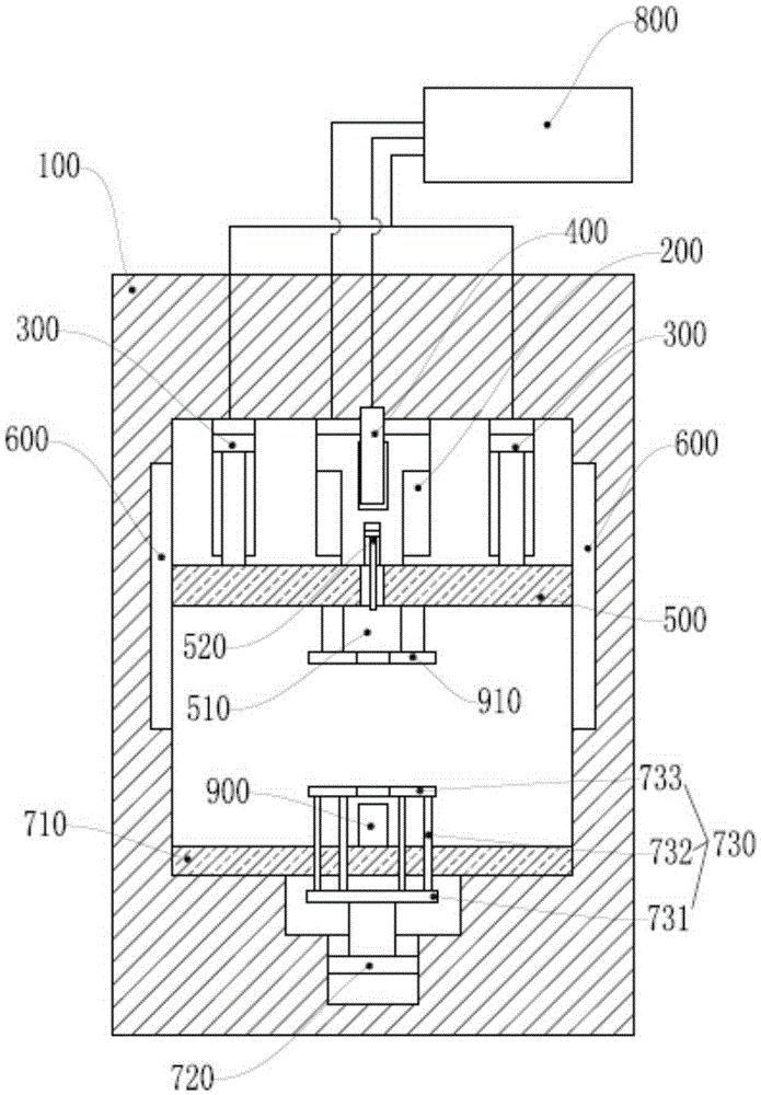
[0018] like figure 1 , a multifunctional combined hydraulic machine, including a frame 100, a main driving cylinder 200, a built-in fast driving cylinder 400, an auxiliary driving cylinder 300, a movable beam 500, a guiding mechanism 600, a workbench 710, a control system, a punch 900 and a die 910; the workbench 710 is fixed on the lower end of the frame 100, the movable beam 500 is slid on the frame 100 through the guide mechanism 600, and is located directly above the workbench 710; the main drive The cylinder 200 is fixed on the upper end of the frame 100, and the piston rod it is provided with is connected with the movable crossbeam 500; The movable crossbeam 500 is connected; the built-in fast driving cylinder 400 is located inside the main driving cylinder 200, one end of which is fixed to t...


PUM


Abstract

The invention relates to the field of metallurgy pressing machines, in particular to a multifunctional combined hydraulic machine. The multifunctional combined hydraulic machine comprises a rack, a main driving cylinder, a built-in rapid driving cylinder, an auxiliary driving cylinder, a movable cross beam, a guide mechanism, a workbench, a control system, a male die and a female die, wherein the workbench is arranged at the lower end of the rack in a sliding way; the movable cross beam is arranged on the upper end of the rack and located right above the workbench; and the main driving cylinder and the auxiliary driving cylinder are connected with the movable cross beam. The action areas of piston rods of the main driving cylinder, the auxiliary driving cylinder and the built-in rapid driving cylinder are unequal, the action area of the piston rod of the main driving cylinder is maximum, and the action area of the piston rod of the built-in driving cylinder is minimum, so that when hydraulic liquid flow amounts are equal, the extension extent of the piston rod of the built-in rapid driving cylinder is maximum, and the extension extent of the piston rod of the main driving cylinder is minimum. According to the multifunctional combined hydraulic machine, under the control of a control system, the hydraulic machine is provided with different feeding speeds and can adapt to the production technology of different materials.

Description

technical field [0001] The invention relates to the field of metallurgical presses, in particular to a multifunctional combined hydraulic press. Background technique [0002] The structure of the traditional hydraulic press is divided into frame (frame, four-column, etc.), main cylinder (movable beam, guide mechanism, upper mold and lower mold, and hydraulic system. The mode of action is: the main cylinder is installed and fixed on the frame, and the movable beam The upper plane is connected with the piston rod of the main oil cylinder, and moves up and down with the extension / retraction of the piston rod, and the guiding precision is controlled by the guiding mechanism, so that the upper die and the lower die cooperate to stretch the sheet. [0003] However, for the above-mentioned traditional hydraulic press, the hydraulic system supplies oil to the main cylinder to generate the required working pressure during work, and the parts are stretched under the slow motion of the...

Claims


Application Information

Patent Timeline
IPC IPC(8): B21D24/00B30B1/34B30B15/16
CPCB30B1/34
Inventor 张悦陈国华何景晖周裕强黎永杰
Owner FOSHAN CONSTANT HYDRAULIC MACHINERY
Why Eureka
Try Eureka