A self-compensating centrifugal expansion high-speed tool holder with mesh tapered sleeve

A centrifugal expansion and self-compensation technology, which is applied in the field of mechanical processing, can solve the problems of low strength and rigidity, uneven contact of the cone surface, poor radial stiffness, etc., to enhance the ability to resist high-frequency chatter, improve the roughness of the processed surface, The effect of reliable two-way constraints

Active Publication Date: 2017-05-31
YANSHAN UNIV
View PDF5 Cites 0 Cited by
  • Summary
  • Abstract
  • Description
  • Claims
  • Application Information

AI Technical Summary

Problems solved by technology

To a certain extent, the connection stiffness between the tool holder and the spindle at high speed is improved, but there are still the following problems: (1) The limit speed is still low; (2) The strength and rigidity are low, and it is easy to deform and break, so it is better to have a hard surface and a tough core. (3) The external expansion clamping mechanism makes the contact of the taper surface uneven, resulting in serious local wear of the taper shank; (4) The hollow structure makes the chuck part of the tool holder move forward, and the tool overhang is large
However, under high-speed rotation, due to the new gap between the taper sleeve and the cylindrical shank, the radial rigidity of this tool holder is still poor under high-speed machining.
[0005] To sum up, to solve the problem of the interface between the spindle and the tool holder, it is necessary not only to ensure the connection performance between the spindle and the tool holder, but also to ensure the dynamic balance accuracy at high speeds. Obviously, the existing tool holders cannot solve this problem well. class questions

Method used


Image

  • A self-compensating centrifugal expansion high-speed tool holder with mesh tapered sleeve
  • A self-compensating centrifugal expansion high-speed tool holder with mesh tapered sleeve
  • A self-compensating centrifugal expansion high-speed tool holder with mesh tapered sleeve

Examples


Embodiment Construction

[0023] The present invention will be further described below in conjunction with accompanying drawing:

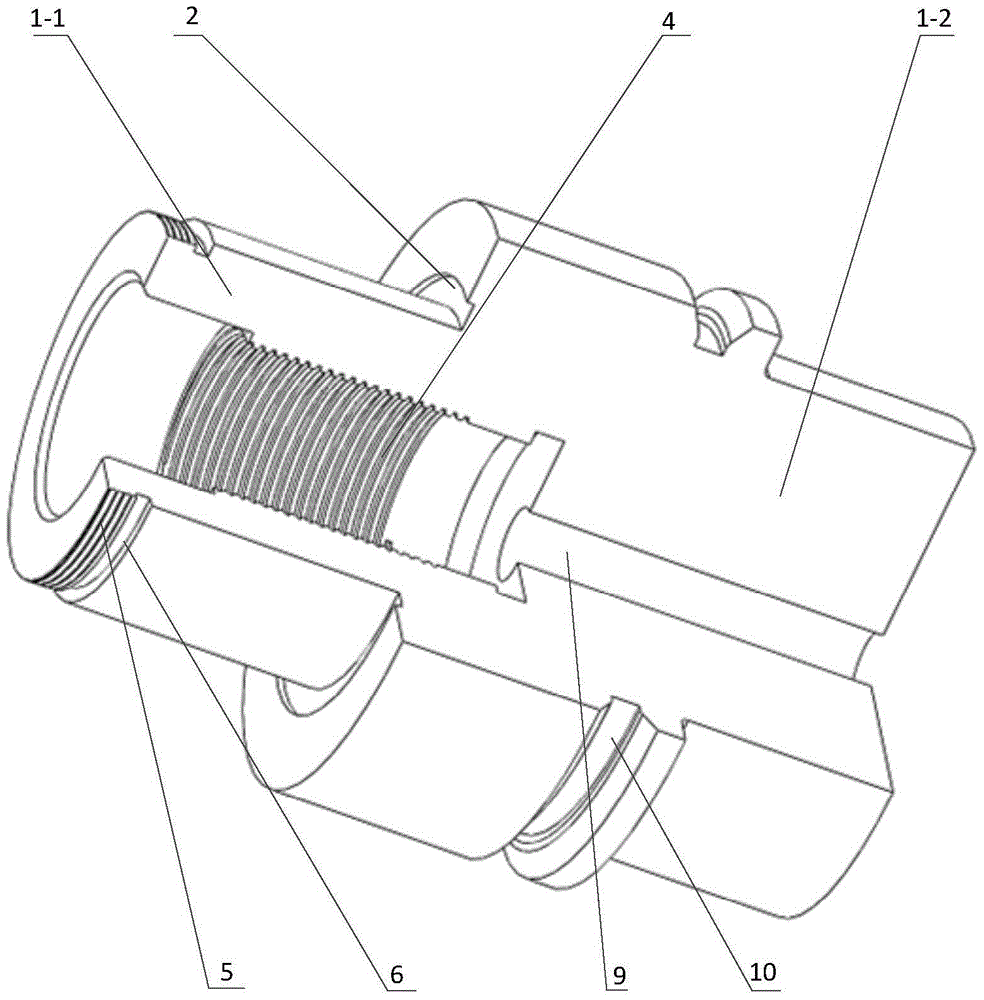
[0024] like figure 1 and 4 As shown, the present invention mainly includes a knife handle handle body 1, which is an integral solid structure composed of a front end handle body 1-1 and a rear end handle body 1-2, and the rear end handle body is compatible with DIN 69893-HSK -E401996-01 tool handle has the same overall dimensions, the front handle body and the rear end handle body are coaxial cylinders, and the diameter of the front end handle body is smaller than the rear end handle body, and the connection around the front end handle body is on the end surface of the rear end handle body A circle of groove 2 is processed at the groove, and a disc spring 3 is installed in the groove; a thread groove 4 is provided from the end surface of the front handle body along the axis to the direction of the rear end handle body, which is used for tension connection with the pull riv...


PUM


Abstract

The invention discloses a net-shaped taper sleeve self-compensating centrifugal expansion high-speed cutter handle. The handle body of the cutter handle is of an integral solid structure consisting of a front end handle body and a rear end handle body; the front end handle body and the rear end handle body are coaxial cylinders; the diameter of the front end handle body is smaller than that of the rear end handle body; a circle of groove is formed in the end surface of the rear end handle body around the connection part of the front end handle body, and a disc spring is arranged in the groove; a threaded groove is formed from the end surface of the front end handle body toward the rear handle handle body along the axis; a shaft shoulder is machined on the front end of the front end handle body and a fine pitch thread and a threaded tool withdrawal groove are formed in the front end handle body; a net-shaped taper sleeve sleeves the outer wall of the front end handle body; a fine pitch lock nut is arranged on the fine pitch thread of the front end handle body in front of the net-shaped taper sleeve; the front end and the rear end of the net-shaped taper sleeve are in contact with the fine pitch thread and the disc spring; a cylindrical clamping groove is formed in the end surface of the rear end handle body along the axis toward the inside; and a V-shaped tool changing groove is formed in the outer wall of the rear end handle body. The net-shaped taper sleeve self-compensating centrifugal expansion high-speed cutter handle has the advantages that the limiting speed is high; the dynamic balance performance is good; the rigid and the position precision are high; the strength is high; and the like.

Description

technical field [0001] The invention relates to the field of machining, in particular to a tool holder for high-speed cutting. Background technique [0002] It is known that a high-speed tool system is a coupling system composed of a main shaft, a tool holder, a collet, a tool and a clamping mechanism, and is used for the connection between the main shaft and the tool. The tool system includes the spindle-tool holder interface and the tool-tool holder interface, the core of which is the tool holder. At present, under the high-speed condition of the traditional BT tool system, due to the action of centrifugal force, the positioning accuracy and joint stiffness are obviously reduced. Under the action of broaching force, the axial position of the tool changes, which affects the machining accuracy and cannot meet the requirements of high-speed machining. [0003] In order to meet the requirements of high-speed cutting machining for tool systems, various advanced high-speed too...

Claims


Application Information

Patent Timeline
Patent Type & Authority Patents(China)
IPC IPC(8): B23Q3/12
CPCB23Q3/12
Inventor 王军马灿范运杰赵连松唐海洋李现华
Owner YANSHAN UNIV
Why Eureka
Try Eureka