Measuring roller and device for measuring an fibers composite

A composite fiber and roller technology, which is applied in the field of composite fiber devices and devices for measuring composite fibers, can solve the problems of measurement signal disappearance, extrusion force weakening, etc., to reduce measurement errors, avoid carrying and offset, The effect of reducing the sticking phenomenon

Active Publication Date: 2016-02-10
RIETER INGOLSTADT GMBH
View PDF7 Cites 3 Cited by
  • Summary
  • Abstract
  • Description
  • Claims
  • Application Information

AI Technical Summary

Problems solved by technology

However, reducing the squeeze force also weakens or completely eliminates the measurement signal

Method used


Image

  • Measuring roller and device for measuring an fibers composite
  • Measuring roller and device for measuring an fibers composite
  • Measuring roller and device for measuring an fibers composite

Examples


Embodiment Construction

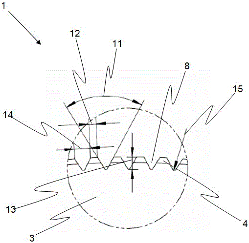
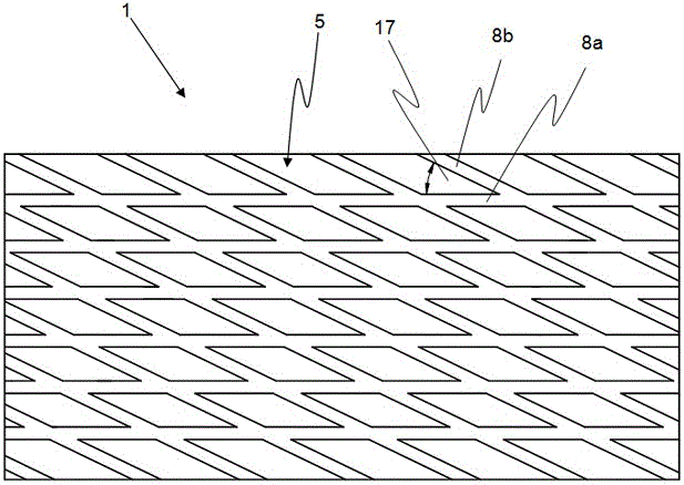
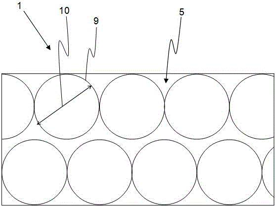
[0066] figure 1 A part of the cross-section of the measuring roll 1 is shown. The measuring roll 1 here consists of a material 3 with a low coefficient of thermal expansion. Furthermore, the outer surface 5 of the measuring roll 1 is coated with a surface coating 4 . Grooves 8 are formed in the outer surface 5 . But as an alternative or in addition to the groove 8, it is also possible to form a hole 9 (such as image 3 shown) and / or bulbous bumps 18 (as Figure 4 shown).

[0067] The surface coating 4 here only partially covers the peaks between the two grooves 8 . Therefore, only the effective surface which is in contact with the composite fiber 6 is coated. It is also conceivable that the grooves 8 are completely coated with the surface coating 4 .

[0068] In addition, the grooves 8 also have an opening angle 11 . Two adjacent grooves 8 each have a distance 12 in the circumferential direction. Likewise, the grooves 8 have a groove depth 13 and a groove width 14 . ...


PUM

PropertyMeasurementUnit
diameteraaaaaaaaaa
depthaaaaaaaaaa
coefficient of linear thermal expansionaaaaaaaaaa

Abstract

The invention relates to a measuring roller for a device for measuring a fiber composite (2), in particular on a draw frame, a carding engine or a comber, made of a material of low thermal expansion (3) and having a surface coating (4), whereas the measuring roller (1) features a shell surface (5) for damping a fiber composite (6) along with a rotary axis (7). In accordance with the invention, the shell surface (5) of the measuring roller (1) features a structure forming an air buffer, made of grooves (8), boreholes (9) and / or spherical projections (18).

Description

technical field [0001] The invention relates to a measuring roll for a device for measuring composite fibers, in particular on a draw frame, a cashmere machine or a combing machine, which measuring roll consists of a material with low thermal expansion and has a surface coating , wherein the measuring roller has an outer cover surface for clamping the composite fiber and an axis of rotation. Furthermore, the invention relates to a device for measuring composite fibers, which has two rotatably mounted measuring rolls with a jacket, wherein the axes of rotation of the measuring rolls are aligned parallel to one another and the composite fibers can be guided through Between the outer surfaces of the measuring rolls, the device also includes a pressing device, by means of which the distance between the measuring rolls can be varied and thus a pressure can be exerted on the composite fibers surrounded by the measuring rolls. Background technique [0002] Measuring systems with s...

Claims


Application Information

Patent Timeline
Patent Type & Authority Applications(China)
IPC IPC(8): D01H13/14D01H5/38G01N33/36
CPCB65H63/06D01H13/32G01N33/365B65H2701/31G01B5/06
Inventor A·克里格勒W·斯莫克伊马德廷·卡拉拉尔
Owner RIETER INGOLSTADT GMBH
Why Eureka
Try Eureka