
Tape expansion device

A technology of expansion device and cutting tape, which is applied in the direction of electrical components, semiconductor/solid-state device manufacturing, circuits, etc., and can solve problems such as job interruption, cutting tape breakage, and scattered devices

Active Publication Date: 2016-02-10
DISCO CORP
View PDF6 Cites 0 Cited by
  • Summary
  • Abstract
  • Description
  • Claims
  • Application Information

AI Technical Summary

Problems solved by technology

[0007] Moreover, in the above-mentioned tape expansion device, the dicing tape may be broken when the dicing tape is expanded, and if the wafer is transferred to the next process in the state where the dicing tape is broken, the devices that are individually divided in the next process will be damaged. Scattered in the device, there is a problem of causing troubles such as interruption of work
[0008] In addition, cutting grooves of a predetermined depth (the depth corresponding to the finished thickness of the device) are formed along the planned dividing line from the surface of the wafer, and then the back surface of the wafer with the cutting grooves formed on the surface is ground, and the cutting grooves are protruded from the surface. After the wafer is divided into individual devices on the back surface, an adhesive film is mounted on the back surface of the wafer, and the dicing tape attached to the adhesive film side is expanded, and the adhesive film is broken along the device. above question

Method used


Image

  • Tape expansion device
  • Tape expansion device
  • Tape expansion device

Examples


Embodiment Construction

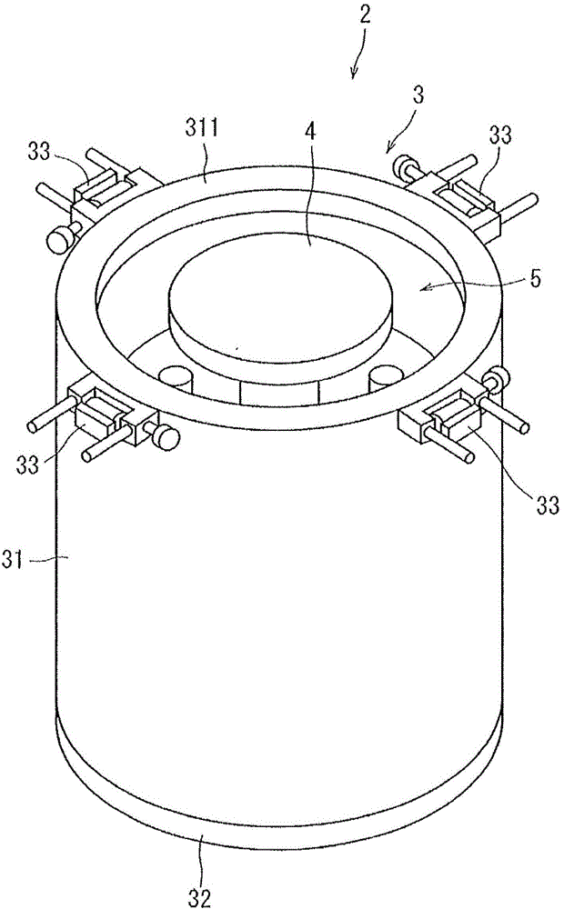
[0027] Hereinafter, preferred embodiments of the band expansion device according to the present invention will be described in detail with reference to the accompanying drawings.

[0028] Image 6 A wafer 10 attached to an upper surface of a dicing tape T made of a synthetic resin film mounted on a ring frame F is shown. In this wafer 10 , a plurality of lines to divide 101 are formed in a grid pattern on a surface 10 a , and devices 102 are formed in a plurality of regions divided by the lines to divide 101 . Positioning the converging point of the pulsed laser light with a wavelength that is transparent to the wafer 10 inside the wafer 10, and irradiating the laser light to the wafer 10 along the planned dividing line 101, the inside of the wafer along the planned dividing line 101. The modified layer 103, which is the starting point of breakage, is continuously formed on the wire. In addition, the modified layer 103 can be formed by the laser processing method disclosed i...


PUM


Abstract

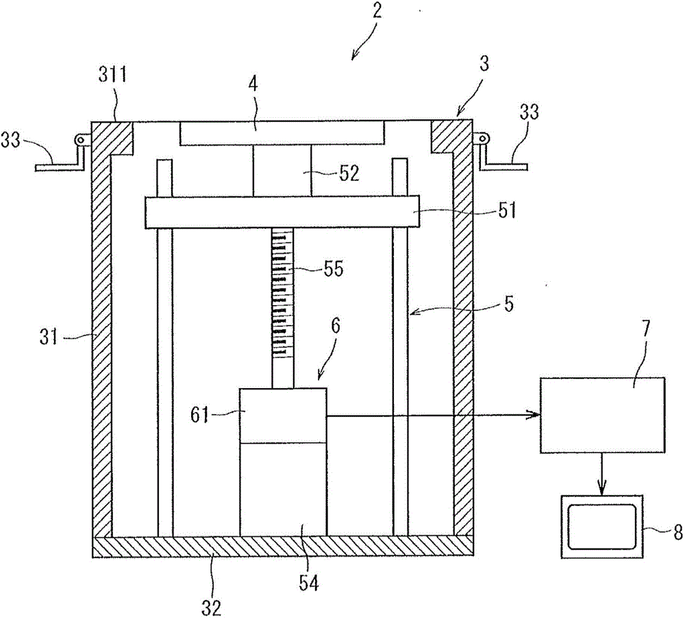
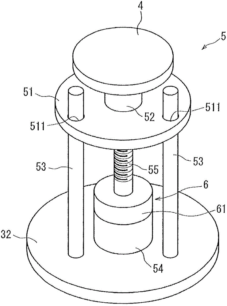
The invention provides a tape expansion device. The tape expansion device comprises a frame maintaining unit, an expansion part, an expansion part work unit, a drive lode detection unit, a control unit and a display unit. The frame maintaining unit is provided with an annular maintaining surface used for maintaining an annular frame. The expansion part has the diameter less than the inner diameter of the annular frame and larger than the diameter of a chip, and acts on a cutting tape mounted on the annular frame on the annular maintaining surface of the frame maintaining unit, and makes the cutting tape expand. The expansion part work unit enables the expansion part to work in the direction perpendicular to the annular maintaining surface of the frame maintaining unit. The drive load detection unit detects the drive load of the expansion part work unit. The control unit determines whether the cutting tape is broken according to a detection signal output by the drive load detection unit. The display unit displays determine results of the control unit. Under a condition that the control unit makes the expansion part work unit works and expands the cutting tape, the control unit determines that the cutting tape is broken according to the detection signal output by the drive lode detection unit when the drive load decreases under a condition that the drive load increases as the cutting tape is expanded.

Description

technical field [0001] The present invention relates to a tape expanding device for expanding a dicing tape on which a wafer on which a plurality of devices is formed on an area divided by a plurality of planned dividing lines is attached and whose outer peripheral portion is attached to a ring frame. Background technique [0002] In the manufacturing process of semiconductor devices, the surface of a generally disk-shaped semiconductor wafer is divided into a plurality of regions by dividing lines formed in a lattice, and devices such as ICs and LSIs are formed in the divided regions. Furthermore, individual devices are manufactured by dividing the semiconductor wafer along lines to divide. [0003] As a method of dividing a workpiece of a wafer such as a semiconductor wafer, the following technology has been put into practical use. The converging point of the pulsed laser beam having transparency to the wafer is positioned inside, and the wafer is irradiated along the line...

Claims


Application Information

Patent Timeline
IPC IPC(8): H01L21/78
CPCH01L21/78
Inventor 中村胜
Owner DISCO CORP
Learn More