M-Bus protector with self-recovery function

A self-recovery, protector technology, applied in the direction of automatic disconnection emergency protection device, protection against overcurrent, emergency protection circuit device, etc., can solve problems such as meter burnout, increased line loss, blown fuse, etc. , to achieve the effect of strong practicability, low insertion loss and low operating current

Inactive Publication Date: 2016-02-10
SHENZHEN JASON DIGITAL TECH CO LTD
View PDF8 Cites 1 Cited by
  • Summary
  • Abstract
  • Description
  • Claims
  • Application Information

AI Technical Summary

Problems solved by technology

Once the debugger connects the M-Bus to the 220V mains by mistake, the meters will burn out in batches, causing major economic losses
In view of the above problems, the method of connecting fuses in series and connecting loads in parallel is usually used to solve the problem. However, this method has the following problems and disadvantages: the overvoltage and overcurrent protection is realized by blown fuses, which cannot be restored by itself, and the fuse must be replaced; different meters The working current needs to be equipped with fuses with different fusing currents, and the passability is not strong; the requirements for the fusing current of the fuse are high, and it cannot play a protective role in the voltage dead zone; the fuse needs to be blown during protection, and there is a fire safety hazard
In addition, the output voltage has no clamping function, and there is a residual voltage output, so the protection effect is easy to fail; and connecting the load in parallel increases the line loss and affects the load capacity of the M-Bus

Method used


Image

  • M-Bus protector with self-recovery function

Examples


Embodiment Construction

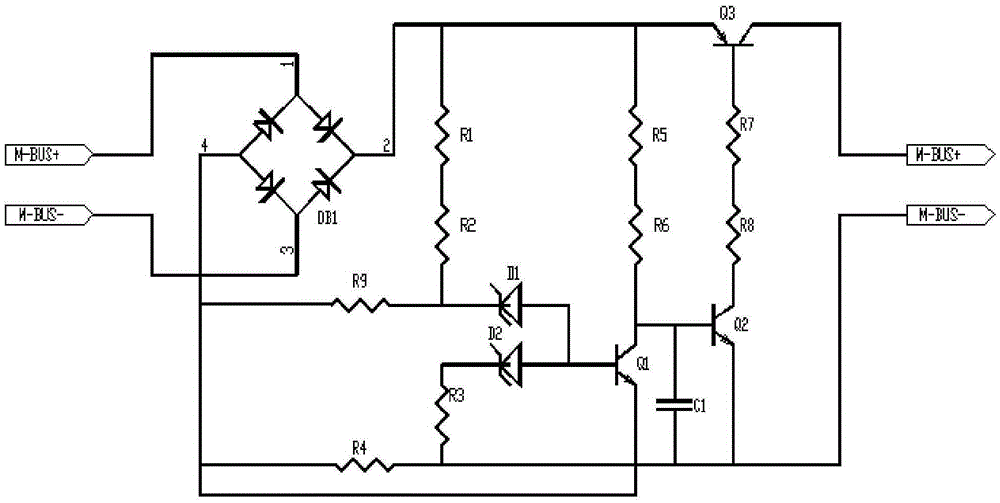
[0032] The present invention will be described below in combination with specific embodiments and with reference to the accompanying drawings.

[0033]An M-Bus bus protector with self-recovery function as shown in the attached figure, the connection mode is between the centralized meter reading equipment and at least one meter, there is no blown fuse, and the load does not need to be connected in parallel. It includes a switching circuit composed of the first switching transistor Q1 of the model MMBTA44, the second switching transistor Q2 of the model MMBTA44 and the third switching transistor Q3 of the model MMBTA94 cascaded in sequence and its DC power supply, connected to the positive and negative DC power supply An inverse voltage divider circuit composed of first divider resistors R1, R2 and second divider resistor R9 between the terminals;

[0034] The DC power supply of the first switch transistor Q1, the second switch transistor Q2 and the third switch transistor Q3 in...


PUM


Abstract

An M-Bus protector with a self-recovery function is disclosed. The M-Bus protector comprises a switch tube formed by a first switch triode, a second switch triode and a third switch triode that are cascaded in sequence, and a direct current power supply and an inversion bleeder circuit of the switch circuit; the base electrode of the first switch triode is connected with an overvoltage threshold valve generating circuit and an overcurrent threshold value generating circuit separately; the emitting electrode of the second switch triode is connected with a connection negative end of meters (such as an intelligent water meter, a gas meter or a calorimeter) and the other end of a delay capacitor; a current-limiting biasing resistor is connected between the collector electrode of the second switch triode and the base electrode of the third switch triode; the emitting electrode of the third switch triode is connected with the positive end of the direct current power supply, and is connected with a centralized meter reading device through the direct current power supply; and the collector electrode of the third switch triode is connected with the connection positive end of the meters. The M-Bus protector can automatically recover to work after faults are eliminated; the M-Bus protector is stable, reliable, and high in practicability; the overall circuit is extremely low in insertion loss and the load capacity of the bus is not affected; and the output voltage is always zero in overvoltage protection, overcurrent protection and short circuit protection, so that the dead zone voltage and the potential safety hazards of fire do not exist.

Description

technical field [0001] The invention relates to an M-Bus bus, in particular to an M-Bus bus protector with a self-recovery function. Background technique [0002] M-Bus is a bus structure specially used for utility meters, called Meter-Bus, or M-Bus for short. In existing centralized meter reading systems such as smart water meters, gas meters, and heat meters (hereinafter referred to as meters), the meters are connected to the centralized meter reading device through the M-Bus bus, and the centralized meter reading device is connected to the centralized meter reading device through wireless, GPRS, etc. The background master station realizes intelligent remote transmission and reading data. The M-Bus interface is a two-wire wiring method. When a meter connected to the M-Bus bus fails, such as excessive operating current or short circuit, all meters under the M-Bus bus will be affected and cannot be copied. When reading data, maintenance personnel or debuggers are checking ...

Claims


Application Information

Patent Timeline
Patent Type & Authority Applications(China)
IPC IPC(8): H02H3/08H02H3/06G06F13/40
Inventor 吴锦洪
Owner SHENZHEN JASON DIGITAL TECH CO LTD
Why Eureka
Try Eureka