
Waste treatment device for laser cutting

A technology of waste treatment and laser cutting, which is applied in laser welding equipment, welding equipment, metal processing equipment, etc., can solve the problems of burning the lens, damaging the optical system, and affecting the processing quality of the workpiece, so as to improve the processing quality and precision and protect the optics. The effect of the system

Active Publication Date: 2016-02-17
SUZHOU SUNSHINE LASER & ELECTRONICS TECH CO LTD
View PDF5 Cites 7 Cited by
  • Summary
  • Abstract
  • Description
  • Claims
  • Application Information

AI Technical Summary

Problems solved by technology

[0003] Existing laser cutting devices only perform laser cutting when processing parts. During the processing, some waste materials such as smoke, dust and processing residues will be attached to the surface of the lens and the workpiece, which affects the processing quality of the workpiece and pollutes the In severe cases, the lens will be burned and the optical system will be damaged

Method used


Image

  • Waste treatment device for laser cutting
  • Waste treatment device for laser cutting
  • Waste treatment device for laser cutting

Examples


Embodiment

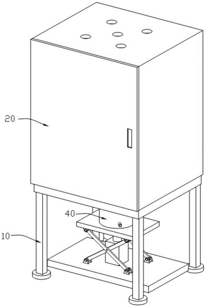
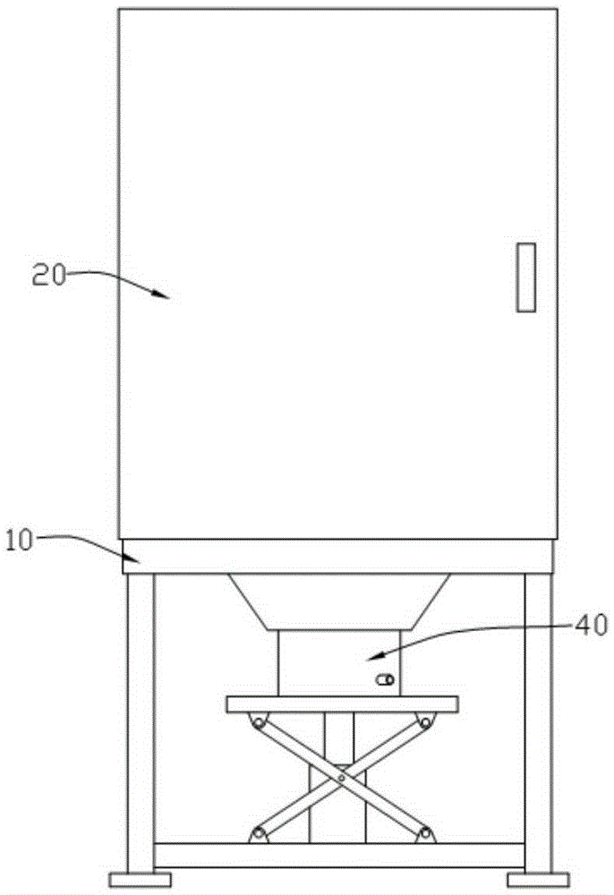
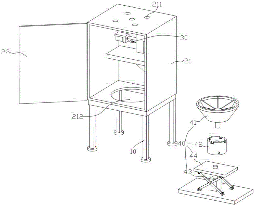
[0024] Examples: The following specific examples illustrate the implementation of the present invention, and those skilled in the art can easily understand other advantages and effects of the present invention from the content disclosed in this specification. The "up" and "down" referred to in this embodiment are consistent with the up and down directions of the drawings themselves; the white hollow arrows in the drawings represent the direction of waste material flow.

[0025] See Figure 1 to Figure 4 As shown, a laser-cut waste material processing device includes: a support frame 10; a casing 20 installed on the support frame 10, which includes a main casing 21, hinged on the main casing 21 and connected to the main casing 21. The main housing 21 is jointly surrounded by a protective door 22 forming an airtight chamber, a workbench 23 and a laser 24 installed in the main housing 21, and the workbench 23 is located in the middle of the main housing 21. The laser 24 is insta...


PUM


Abstract

The invention discloses a waste treatment device for laser cutting. The waste treatment device comprises a supporting frame, a housing mounted on the supporting frame, a waste blowing device and a waste receiving device, wherein the housing comprises a main housing, a protective door which is hinged on the main housing and forms a sealed chamber together with the main housing, and a workbench and a laser unit which are mounted in the main housing; the top end surface and the bottom end surface of the main housing are respectively provided with a hole part for taking in air and a central hole for discharging air; the waste blowing device is mounted in the main housing, positioned at one side of the workbench and used for blowing off waste generated by laser cutting from the workbench; and the material receiving device is arranged below the housing for collecting the waste. The waste treatment device can be used for effectively treating waste such as smoke dust, residues and the like generated in a laser cutting process, and has the advantages of protecting an optical system and improving processing quality and precision of a workpiece.

Description

Technical field: [0001] The invention relates to the technical field of laser drilling machines, in particular to a waste material processing device for laser cutting. Background technique: [0002] Laser drilling is the earliest practical laser processing technology, and it is also one of the main application fields of laser processing. With the rapid development of modern industry and science and technology, more and more materials with high hardness and high melting point are used, while traditional processing methods can no longer meet certain process requirements. This type of processing task is very difficult, sometimes even impossible, with conventional machining methods, but it is not difficult to achieve with laser drilling. The laser beam is highly concentrated in space and time. Using the lens to focus, the diameter of the spot can be reduced to the micron level to obtain a laser power density of 105-1015W / cm2. Generally, a laser drilling machine is composed of ...

Claims


Application Information

Patent Timeline
Patent Type & Authority Applications(China)
IPC IPC(8): B23K26/38B23K26/142
CPCB23K26/38
Inventor 王荣郭学亮
Owner SUZHOU SUNSHINE LASER & ELECTRONICS TECH CO LTD
Learn More