
Construction method of complicated beam column joint core area

A construction method and technology of beam-column joints, which are applied in the directions of construction, building structure, and building materials, etc., can solve the problem that the construction quality of the core area of ​​beam-column joints is difficult to obtain due guarantee, the welding operation surface of the steel bars at the bottom of the beam is insufficient, It is difficult to control the welding quality of ribbed plates, etc., so as to ensure the first pass rate of concealed acceptance, improve the construction quality, and achieve the effect of high forming rate at one time of construction

Inactive Publication Date: 2016-02-17
徐仁贵
View PDF5 Cites 9 Cited by
  • Summary
  • Abstract
  • Description
  • Claims
  • Application Information

AI Technical Summary

Problems solved by technology

[0003] The emergence of steel concrete and prestress plays a prominent role in realizing "large-span space" for building structures. However, when steel beams, steel columns, prestress, and even multi-beam intersections appear at the same time, the construction process is complicated and the construction is difficult. In particular, the construction quality of the core area of ​​such complex beam-column joints is difficult to get due guarantee
The beam-column core area of ​​such complex joints often has dense and intricately arranged steel bars, difficult to meet the anchorage length of the steel bars, difficult to control the welding quality with the rib plate, insufficient welding operation surface for the steel bars at the bottom of the beam, and difficult to control the opening ratio of the steel members. The superimposed arrangement of steel bars leads to construction problems such as super-high slabs

Method used


Image

  • Construction method of complicated beam column joint core area
  • Construction method of complicated beam column joint core area
  • Construction method of complicated beam column joint core area

Examples


Embodiment Construction

[0027] The technical solutions in this application will be clearly and completely described below in conjunction with the accompanying drawings. Apparently, the described embodiments are only some of the embodiments of this application, not all of them. Based on the embodiments in the present application, all other embodiments obtained by persons of ordinary skill in the art without making creative efforts belong to the protection scope of the present application.

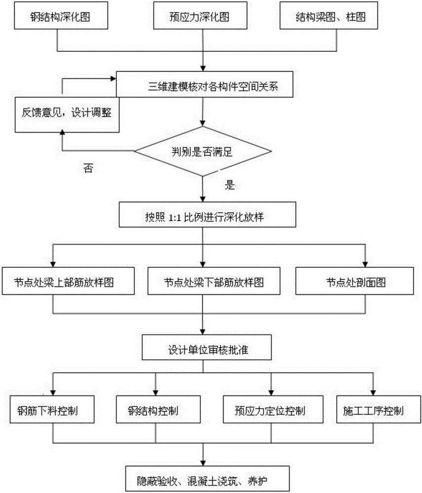
[0028] Such as figure 1 As shown, the complex beam-column joint core area construction method of the present invention comprises the following steps:

[0029] A. Carry out comprehensive deepening and lofting of steel structure deepening diagram, prestressed deepening diagram, structural beam diagram and column diagram, use computer to carry out three-dimensional modeling and plane lofting of nodes, check the spatial relationship between each component, and judge whether it meets the design requirements, If it is n...


PUM


Abstract

The invention relates to a construction method of a complicated beam column joint core area. The construction method comprises the following steps of carrying out integrated deepened lofting on a steel structure deepening figure, a prestress deepening figure, a structure beam figure and a column figure; carrying out three-dimensional modeling and planar lofting on joints by using a computer; carrying out deepening lofting according to the ratio of 1:1; manufacturing a lofting figure of ribs on upper portions of beams at the positions of the joints, a lofting figure of ribs on the lower portions of the beams at the positions of the joints and a profile map at the position of each joint; and controlling feeding of reinforcing steel bars, steel structures, prestress and construction procedures. An optimized principle of considering the reinforcing steel bars at first and then considering cross sections is adopted, and respective anchoring of supports is avoided; when beam steels cannot penetrate through the joints, the joint core area is anchored; when the beam steels cannot penetrate through the joints or cannot be anchored, the beam steels are welded with profile steel rib lapping plates; and through concealed check acceptance, concrete pouring and maintaining are carried out. By the construction method, construction quality can be guaranteed effectively.

Description

technical field [0001] The invention relates to a construction method for the core area of ​​complex beam-column joints, belonging to the technical field of building construction. Background technique [0002] With the continuous emergence of various new structural forms in my country's architectural field, the methods of structural design have gradually become diversified. From the design point of view, it is necessary to ensure the "safety and firmness" of the physical structure while also ensuring the "functional use, beautiful and exquisite" of the formed building. Undoubtedly, with the continuous development of my country's construction industry, large-scale commercial complex projects Expectations for the latter are also constantly increasing, that is to say, on the premise of meeting the "limit state of bearing capacity", users have a deeper understanding and requirements for the "limit state of normal use" of the building. In order to cater to the development trend o...

Claims


Application Information

Patent Timeline
IPC IPC(8): E04G21/00E04G21/12E04G21/14E04B1/58
CPCE04G21/00E04B1/58E04G21/12E04G21/14
Inventor 徐仁贵
Owner 徐仁贵
Features
  • Generate Ideas
  • Intellectual Property
  • Life Sciences
  • Materials
  • Tech Scout
  • Unparalleled Data Quality
  • Higher Quality Content
  • 60% Fewer Hallucinations
Learn More