
Handheld lubrication system for four-stroke engine

A four-stroke engine and lubrication system technology, applied in the direction of engine lubrication, engine components, valve accessories lubrication, etc., can solve problems such as lubrication of running parts that are not well guaranteed, oil burning, availability, etc., to achieve the effect of oil and gas separation Good, low lubricating oil loss, good lubricating effect

Active Publication Date: 2016-02-17
ZHEJIANG ZHONGJIAN TECH
View PDF9 Cites 0 Cited by
  • Summary
  • Abstract
  • Description
  • Claims
  • Application Information

AI Technical Summary

Problems solved by technology

[0003] During the use of the hand-held four-stroke engine, the following problems will occur: First, when the engine is working, it is necessary to ensure that the crankshaft connecting rod mechanism, the gas distribution mechanism and other operating parts are reliable, and it is necessary to ensure that each operating mechanism is fully equipped. oil to ensure lubrication, but the current lubrication system in each operating mechanism, the lubrication is not very ideal; second, the engine does not ensure the lubrication of each operating part when the engine is turned over at will, or the oil will flow with the gas Entering the air filter together will cause oil burning, which will affect the working efficiency of the machine
For this reason, many manufacturers and people of insight have carried out research and development on the above-mentioned problems, but no more reasonable products have come out so far.

Method used


Image

  • Handheld lubrication system for four-stroke engine
  • Handheld lubrication system for four-stroke engine
  • Handheld lubrication system for four-stroke engine

Examples


Embodiment Construction

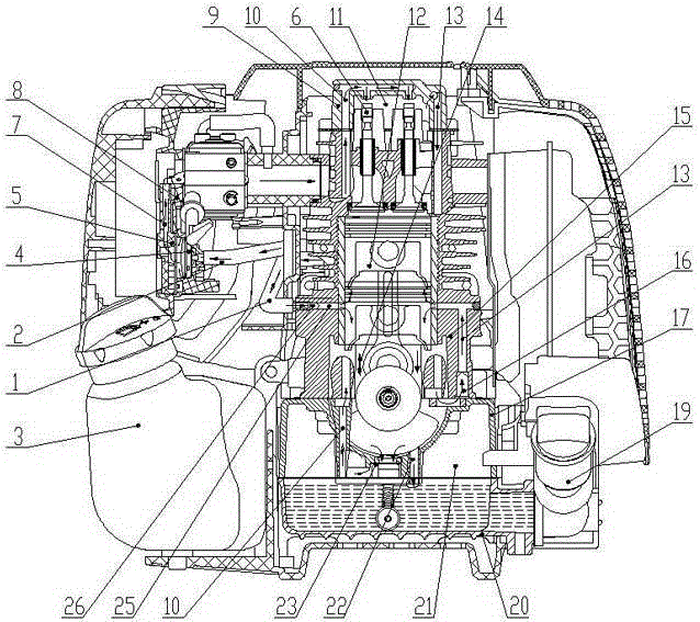
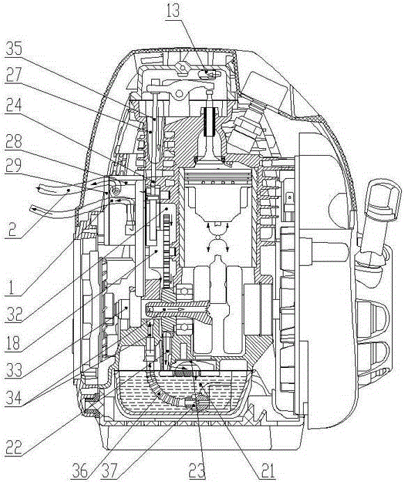
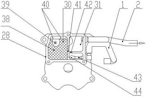
[0024] Figure 1 to Figure 5 Shown is a specific implementation of the lubrication system of a handheld four-stroke engine created by the present invention, which includes an oil sump 20 and a tank body 17 consisting of an oil storage chamber 21, and a crankshaft chamber consisting of a tank body 17 and a cylinder block 15 14. Rocker valve chamber 11 composed of cylinder block 15 and cylinder head cover 9, cam chamber 32 composed of cylinder block 15 and cam side cover 28, tappet chamber 27 attached to the side of cylinder block 15, air filter 8, fuel tank 3 , The oil pan 20 is connected to the organic oil port 19, the cylinder block 15 is provided with a piston assembly 12, the crank chamber 14 is provided with a crankshaft connecting rod assembly 33, the rocker arm valve chamber 11 is provided with a rocker arm valve assembly 6, and a tappet chamber 27 A tappet assembly 35 is provided, a cam assembly 18 is provided in the cam chamber 32, and an oil suction passage 34 connectin...


PUM


Abstract

The invention discloses a handheld lubrication system for a four-stroke engine. The handheld lubrication system for the four-stroke engine comprises an oil storage chamber (21), a crankshaft chamber (14), a rocker arm air valve chamber (11), a cam chamber (32), a tappet chamber (27) and an oil-gas separating device. A box body (17) and a crankshaft connecting rod assembly (33) are provided with an oil sucking oil channel (34) communicated with the oil storage chamber (21) and the crankshaft chamber (14). The box body (17), an air cylinder body (15) and a cylinder head cover (9) are provided with an oil pumping channel (10) communicated with the crankshaft chamber (14) and the rocker arm air valve chamber (11) through a first one-way valve (23). The cylinder head cover (9), the air cylinder body (15) and the box body (17) are provided with a first oil returning channel (13) connected with the rocker arm air valve chamber (11) and the crankshaft chamber (14) through a second one-way valve (16). A third oil returning channel (25) is arranged between the oil-gas separating device and the crankshaft chamber (14) through a third one-way valve (26). By means of the structure, the handheld lubrication system for the four-stroke engine has the characteristics of being simple and compact in structure, high in lubrication efficiency, good in oil-gas separation effect, capable of being operated normally by an operator with random gestures.

Description

Technical field [0001] The invention relates to a hand-held four-stroke engine, in particular to a lubrication system of a hand-held four-stroke engine that can run in any posture. Background technique [0002] With the continuous development of society and the advancement of science and technology, various garden tools and small agricultural institutions have been continuously transformed, upgraded and updated. The demand for small gasoline engines in gardens and agriculture has continued to increase. At present, the market is still in the second place that can work in any direction. Mainly use stroke engines, but as environmental problems become increasingly severe and emission requirements continue to increase, handheld four-stroke engines will inevitably replace two-stroke engines in the future. [0003] During the use of a handheld four-stroke engine, the following problems will occur: First, when the engine is working, it is necessary to ensure that the crankshaft connecting ...

Claims


Application Information

Patent Timeline
IPC IPC(8): F01M1/04F01M1/06F01M9/10F01M11/06F01M11/08
CPCF01M1/04F01M1/06F01M9/10F01M11/062F01M11/08F01M2001/062F01M2001/066
Inventor 王浦亮胡寿仁张力徐明智周彪吴潘浩
Owner ZHEJIANG ZHONGJIAN TECH
Learn More