Engine piston
An engine and piston technology, applied in the field of engine component structure design, can solve the problems of heavy piston weight, high piston compression, and difficult processing, and achieve the effects of reducing piston weight, reducing piston compression height, and saving materials
- Summary
- Abstract
- Description
- Claims
- Application Information
AI Technical Summary
Problems solved by technology
Method used
Image
Examples
Embodiment 1
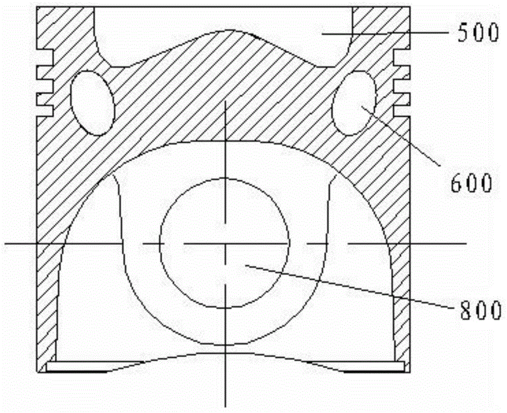
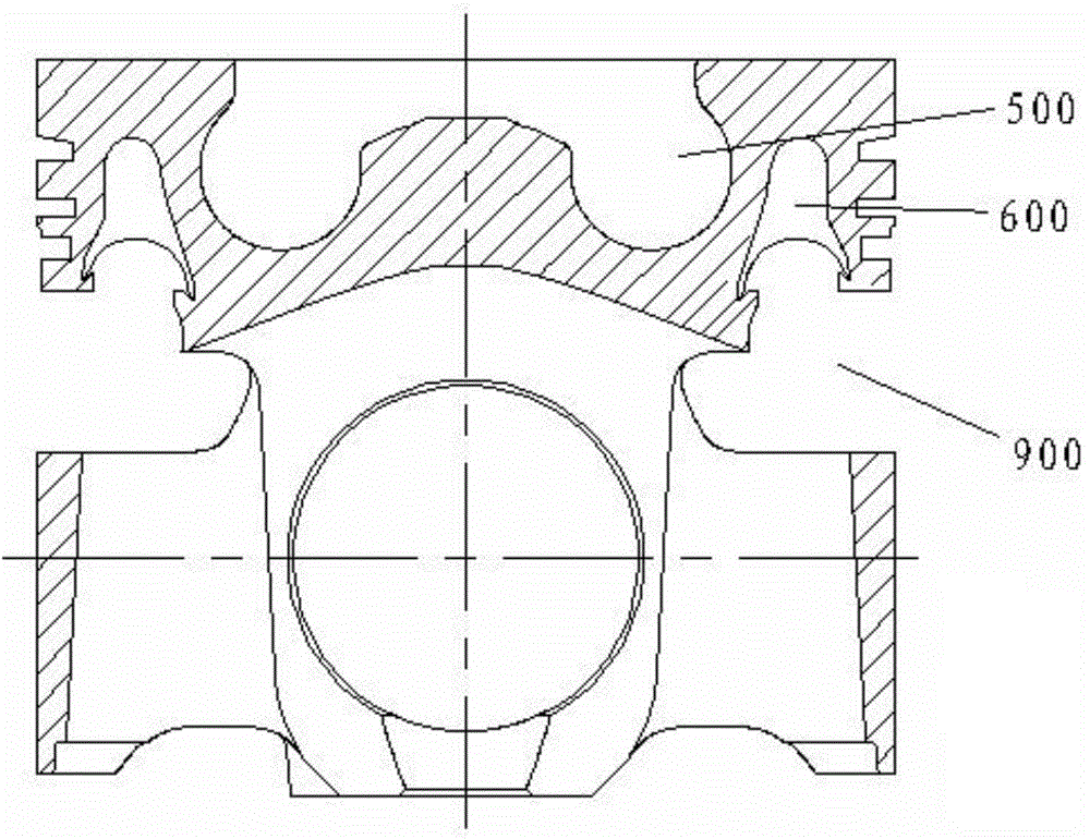
[0079] See Figure 5-Figure 12 , these figures provide a schematic structural view of the engine piston of the present embodiment.
[0080] In this embodiment, the piston head 1 and the piston skirt 2 are hinged and fixed to form a three-pin seat hinged piston. The piston in this embodiment preferably adopts a steel top aluminum / iron skirt structure.
[0081] Align the finished piston head 1 with the installation position of the piston skirt 2, and the piston pin passes through the pin seat hole 8 of one side skirt, the pin hole 11 of the middle pin seat 7, and the pin on the other side of the piston skirt 2. The seat hole 8 connects the piston head 1 and the piston skirt 2, and the top end surface of the piston skirt 2 is not in contact with the piston head 1, thus completing the assembly of the three-pin seat articulated piston.
[0082] The piston head 1 is forged, and the ring groove 4, combustion chamber 5, and internal cooling oil passage 6 of the piston head 1 are con...
Embodiment 2
[0086] See Figure 13-Figure 19 , these figures provide a schematic structural view of the engine piston of the present embodiment.
[0087] In this embodiment, the piston head 1 and the piston skirt 2 are friction welded to form a three-pin seat integral piston. In this embodiment, the piston preferably adopts an all-steel structure.
[0088] The three-pin seat integral piston is composed of a piston head 1 and a piston skirt 2, which are connected by friction welding. Align the welding joints 15 of the piston head 1 and the piston skirt 2, and perform friction welding on the piston head 1 and the piston skirt 2 by a friction welding machine, and the piston head 1 and the piston skirt 2 are semi-finished products after welding. Wherein, one end of the piston skirt 2 facing the piston head 1 is provided with an annular connecting portion extending toward the axial direction of the skirt; The ring groove structure; through the friction welding between the connecting part and...
Embodiment 3
[0094] See Figure 20-Figure 27 , these figures provide a schematic structural view of the engine piston of the present embodiment.
[0095] In this embodiment, the piston head 1 and the piston skirt 2 are friction welded to form a three-pin seat elastically articulated piston. The piston in this embodiment preferably adopts a steel top aluminum skirt structure.
[0096] The finished piston head 1 is aligned with the installation position of the piston skirt 2. After the piston head 1 and the piston skirt 2 are connected by pins, the lower end surface of the piston head 1 and the piston skirt 2 There is a gap between the top end faces. Between the piston head 1 and the piston skirt 2 is arranged a belleville spring 3 which is partially elastically deformed in the gap in the axial direction of the piston. The piston pin passes through the pin seat hole 8 of one side skirt, the pin hole 11 of the middle pin seat 7, and the pin seat hole 8 of the other side of the piston skirt...
PUM
 Abstract
Description
Claims
Application Information
 - R&D
- Intellectual Property
- Life Sciences
- Materials
- Tech Scout
- Unparalleled Data Quality
- Higher Quality Content
- 60% Fewer Hallucinations
Browse by: Latest US Patents, China's latest patents, Technical Efficacy Thesaurus, Application Domain, Technology Topic, Popular Technical Reports.
© 2025 PatSnap. All rights reserved.Legal|Privacy policy|Modern Slavery Act Transparency Statement|Sitemap|About US| Contact US: help@patsnap.com


