
Explosion-proof and leak-proof magnetic suspension fan

A magnetic levitation and magnetic levitation bearing technology, applied in mechanical equipment, machines/engines, liquid fuel engines, etc., can solve problems such as rotor agitation loss, pipeline eddy current loss, and parts corrosion, and achieve a wide range of applications

Active Publication Date: 2016-02-17
NANJING CIGU TECH CORP LTD
View PDF7 Cites 9 Cited by
  • Summary
  • Abstract
  • Description
  • Claims
  • Application Information

AI Technical Summary

Problems solved by technology

High-speed motors have high speed, high efficiency, and small size, but the high power density leads to higher heat generation per unit volume, so the heat dissipation problem is difficult to solve
The cooling effect of air cooling is poor, which is not conducive to the explosion protection of the motor
The effect of installing a water-jacketed liquid cooling system on the casing is better than that of air cooling, but the method of indirectly cooling internal parts through cooling the casing still cannot meet the heat dissipation requirements of high-power high-speed motors
Passing the coolant into the motor can effectively cool the motor, but it is easy to cause problems such as parts corrosion, eddy current loss of the pipeline, and stirring loss of the rotor. At the same time, the coolant is also easy to leak out from the bearing

Method used


Image

  • Explosion-proof and leak-proof magnetic suspension fan
  • Explosion-proof and leak-proof magnetic suspension fan

Examples


Embodiment Construction

[0019] The present invention will be further described below in conjunction with the accompanying drawings.

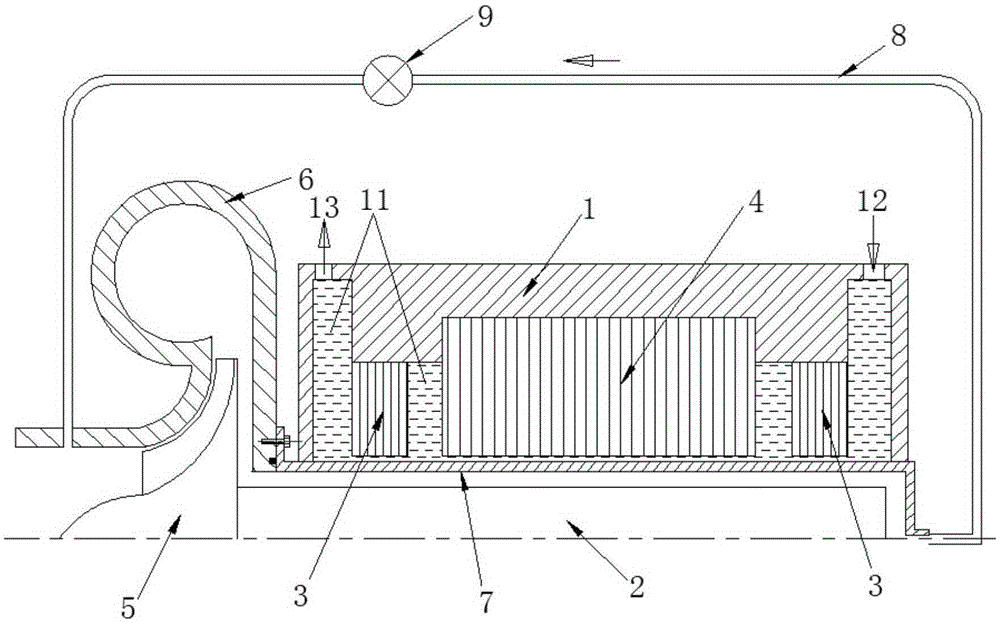
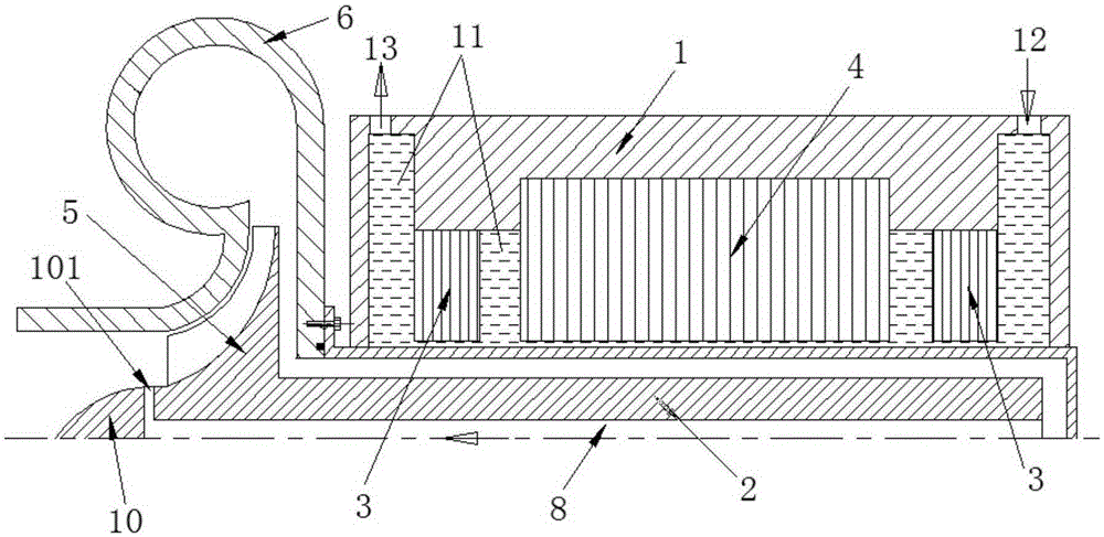
[0020] like figure 1 As shown, the explosion-proof and leakage-proof magnetic levitation fan of the present invention includes a casing 1, a rotor 2, a magnetic suspension bearing 3, a stator 4, an impeller 5 and a volute 6, the magnetic suspension bearing 3 and the stator 4 are all supported in the casing 1, and the rotor 2 rotates It is arranged in the magnetic suspension bearing 3 and the stator 4, and the left end of the rotor 2 extends out of the casing 1 and is fixedly connected with the impeller 5, which is arranged in the volute 6. A sheath 7 is provided in the inner cavity of the casing 1. The sheath 7 is a barrel-shaped structure with one end open and the other end closed. The sheath 7 is arranged between the rotor 2 and the casing 1 to connect the rotor 2 to the magnetic suspension Bearing 3 and stator 4 are separated. The left end of the sheath 7 extends ...


PUM


Abstract

The invention discloses an explosion-proof and leak-proof magnetic suspension fan. The explosion-proof and leak-proof magnetic suspension fan comprises a shell, a rotor, magnetic suspension bearings, a stator, an impeller and a volute, wherein the magnetic suspension bearings and the stator are born in the shell; the rotor is arranged in the magnetic suspension bearings and the stator, and one end of the rotor stretches out of the housing and is fixedly connected with the impeller; and the impeller is arranged in the volute. The explosion-proof and leak-proof magnetic suspension fan further comprises a backflow tube and a sheath, wherein the sheath is arranged in an inner cavity of the housing, and located between the rotor and the magnetic suspension bearings and between the rotor and the stator; an open end of the sheath stretches out of the housing and is fixedly connected with the volute, and penetrates through the inner cavity of the volute; the backflow tube is arranged outside the housing, one end of the backflow tube is communicated with the sheath, and the other end of the backflow tube is communicated with the volute; a cooling liquid flow channel is arranged in the shell and located at one side of each magnetic suspension bearing and one side of the stator; the cooling liquid flow channel penetrates through the inner cavity of the shell; and a liquid inlet and a liquid outlet which penetrate through the cooling liquid flow channel are arranged in the wall of the shell. The explosion-proof and leak-proof magnetic suspension fan disclosed by the invention utilizes the advantages of high speed and high efficiency of the suspension bearings, and achieves a good cooling effect.

Description

Technical field: [0001] The invention relates to a magnetic levitation fan, in particular to an explosion-proof and leakage-proof magnetic levitation fan. Background technique: [0002] With the development of high-speed and high-efficiency fans, low-friction and high-speed suspension bearings are more and more widely used. However, the inherent defects of suspension bearings also limit the application of such fans in the fields of explosion-proof, waterproof, high vacuum, high cleanliness, and toxic gases. [0003] Suspension bearings generally include magnetic suspension bearings, air suspension bearings, oil bearings, etc. Among them, the air suspension bearing and the oil bearing use the fluid pressure difference in the gap between the shaft and the bearing pad to suspend the shaft near the center of the bearing pad, and the magnetic suspension bearing uses the electromagnetic field to suspend the shaft. Their common feature is that there must be a certain gap between ...

Claims


Application Information

Patent Timeline
IPC IPC(8): F04D25/08F04D29/00F04D29/058F04D29/58F04D29/08F04D29/70
Inventor 胡思宁李健吴立华董继勇
Owner NANJING CIGU TECH CORP LTD
Learn More