Liquefied natural gas gasifier detachably connected with internal and external heat exchange sheets

A technology of liquefied natural gas, disassembly and connection, which is applied in the field of liquefied natural gas transportation, can solve the problems of poor gasification effect, non-adjustable gas transmission speed, etc., and achieve good heat absorption effect

Inactive Publication Date: 2016-02-17
ZHEJIANG OCEAN UNIV
View PDF8 Cites 2 Cited by
  • Summary
  • Abstract
  • Description
  • Claims
  • Application Information

AI Technical Summary

Problems solved by technology

[0004] The invention provides a liquefied natural gas vaporizer with good gasification effect, adjustable gasification effect, gasification effect can be assembled according to needs, and gas transmis

Method used


Image

  • Liquefied natural gas gasifier detachably connected with internal and external heat exchange sheets
  • Liquefied natural gas gasifier detachably connected with internal and external heat exchange sheets
  • Liquefied natural gas gasifier detachably connected with internal and external heat exchange sheets

Examples


Embodiment 1

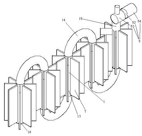
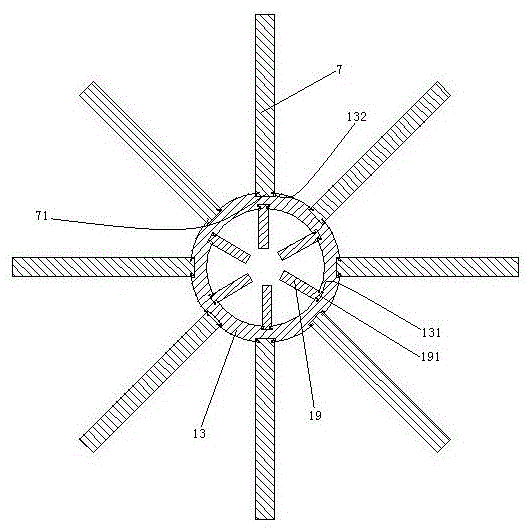
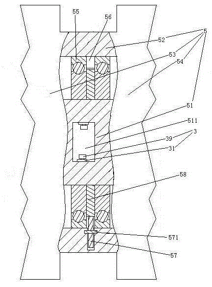
[0033] Embodiment one, see figure 1 , a liquefied natural gas vaporizer detachably connected with internal and external heat exchange fins, including a vaporization pipe 1 and a delivery pump 5 . The gasification tube 1 is a circular tube. The chemical tube 1 includes several gasification sections 13 and bending sections 14 . Specifically, there are four gasification sections 13 and four bending sections 14 . The gasification section 13 has a linear structure, that is, a straight pipe. The gasification section 13 and the bending section 14 are arranged at intervals so that the gasification tube 1 forms a folded structure. The outer surface of the gasification section 13 is provided with several outer heat exchange fins 7 . The outer heat exchange fins 7 are distributed along the circumference of the gasification section 13 . Delivery pump 5 is existing structure. The feed pump 5 includes a pump housing 52 . Both ends of the pump casing 52 are provided with a delivery pu...

Embodiment 2

[0044] Embodiment two, the difference with embodiment one is:

[0045] see Figure 8 , each gasification section 13 is provided with a self-cutting switch 9 for dumping. All pouring self-cutting switches are connected in series for controlling the motor 54 of the delivery pump 5 to stop.

[0046] The tilt self-cutting switch 9 includes a shell 91 and a connecting pin 92 . The shell 91 is fixedly connected with the gasification section 13 .

[0047] see Figure 9 , The tilt self-disconnecting switch 9 also includes a power-disconnecting spring 93 , a conductive sheet 94 , a weight guide cavity 95 , a weight 96 , a swing arm 97 and a barb 98 .

[0048] The shell 91 is made of insulating material, specifically made of plastic. The housing 91 is provided with an assembly cavity 911 . A recess 915 is formed in the middle of the bottom wall of the assembly cavity 911 .

[0049] There are two connecting pins 92. The two connecting pins 92 are distributed along the left and ri...

Embodiment 3

[0058] Embodiment three, the difference with embodiment two is:

[0059] see Figure 12 , A number of outlet holes 11 are provided on the peripheral surface of the outlet end 16 of the gasification tube. A tube base 12 is connected to the outer end of the air outlet hole 11 . The tube base 12 and the outlet end 16 of the gasification tube are welded together. The inner pipe 4 is pierced in the air outlet hole 11 . The inner end of the inner tube 4 is provided with a flange 41 . The inner tube 4 passes through the tube base 12 and then passes into and out of the trachea 2 .

[0060] see Figure 13 , the flange 41 is hooked on the inner peripheral surface of the outlet end 16 of the gasification tube. The flange 41 and the inner peripheral surface of the outlet end 16 of the gasification tube are only connected together by abutting. The junctions of the pipe base 12 , the inner pipe 4 and the outlet pipe 2 are welded together to form a weld 6 . The weld seam 6 seals and ...


PUM


Abstract

The invention relates to a gasifier. The liquefied natural gas gasifier detachably connected with internal and external heat exchange sheets comprises a gasification tube and a conveying pump which is connected with the inlet end of the gasification tube and is adjustable in conveying speed; the gasification tube comprises at least two gasification sections of straight line structures; and the gasification sections and bending sections are arranged at intervals to form a folding-back structure. A plurality of internal heat exchange sheets are connected into the gasification sections in a pluggable manner, and a plurality of external heat exchange sheets are connected with the outer side of the gasification sections in a pluggable manner. According to the liquefied natural gas gasifier detachably connected with the internal and external heat exchange sheets, the gasification effect is good and adjustable, the gasification effect can be achieved according to needs, and the gas conveying speed can be adjusted according to needs; and the problems that an existing liquefied natural gas gasifier is not adjustable in gas conveying speed and poor in gasification effect are solved.

Description

technical field [0001] The invention relates to a vaporizer, in particular to a liquefied natural gas vaporizer detachably connected with internal and external heat exchange fins, and belongs to the technical field of liquefied natural gas transportation. Background technique [0002] Liquefied natural gas is transported to the gas storage station by a special liquefied gas transport vehicle after the temperature is lowered below minus 140 degrees, and loaded into the low-temperature insulation tank of the gas storage station. The gas storage tank (actually stored in a liquid state) flows out the liquid liquefied natural gas through the pipe, and then exchanges the cooling capacity with the external environment through the liquefied natural gas vaporizer, so that the temperature of the liquefied gas rises, so as to realize the exit at the outlet section of the vaporizer Gaseous natural gas is then supplied to users through pipelines. In the Chinese patent application number...

Claims


Application Information

Patent Timeline
IPC IPC(8): F17C7/04F17C13/00F28F1/42
Inventor 刘艳萍刘先勇胡海燕
Owner ZHEJIANG OCEAN UNIV
Why Eureka
Try Eureka