
Insertion core device and manufacture method thereof

A manufacturing method and ferrule technology, which is applied in the field of ferrule device and ferrule device manufacturing, can solve the problems affecting the optical performance of optical fiber, cannot be cleaned, and the fiber is broken, so as to achieve the effect that the optical performance is not affected and the cleanliness is guaranteed

Inactive Publication Date: 2016-02-17
TYCO ELECTRONICS (SHANGHAI) CO LTD
View PDF5 Cites 7 Cited by
  • Summary
  • Abstract
  • Description
  • Claims
  • Application Information

AI Technical Summary

Problems solved by technology

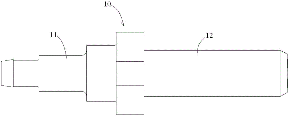
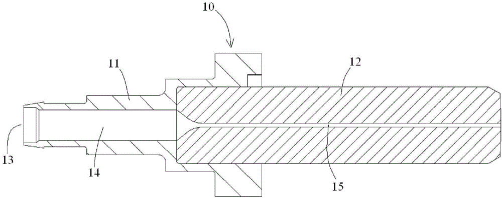
[0005] In the existing technical scheme, since the adhesive is first injected into the accommodation cavity 14 of the ferrule assembly 10, and then the optical fiber is passed through the accommodation cavity 14 of the ferrule assembly 10 filled with the adhesive, bonding As the optical fiber is inserted, the gap between the optical fiber and the wall of the fiber insertion hole 15 of the ferrule assembly 10 is filled. This technical solution is simple and effective, and is widely used. Tendency to vary in size, which results in inconsistent removal of the adhesive pack prior to grinding the front face of the ferrule assembly 10, complicating processing
At the same time, since the adhesive is injected first and then the optical fiber is threaded, the adhesive injected first will produce certain resistance to the penetration of the optical fiber, especially when the optical fiber insertion hole 15 is small, when the optical fiber is inserted into the ferrule assembly 10 During the process of optical fiber, it is easy to cause dark damage to the optical fiber, or even break the optical fiber, resulting in an increase in the scrap rate or affecting the long-term reliability of the optical fiber connector.
In particular, when the surface of the optical fiber protruding from the front face of the ferrule assembly 10 must be presented in an adhesive-free state, although in theory it is possible to perform a certain degree of cleaning on the protruding bare fiber end to remove the adhesive material However, when cleaning the bare fiber, the bare fiber protruding from the front end of the ferrule is prone to mechanical damage or breakage caused by the cleaning action. Therefore, in order to protect the bare fiber from mechanical damage or breakage, it cannot be sufficiently cleaned. The cleanliness of the bare fiber protruding from the front end of the ferrule (adhesive-free level) does not meet the requirements, which affects the optical performance of the fiber

Method used


Image

  • Insertion core device and manufacture method thereof
  • Insertion core device and manufacture method thereof
  • Insertion core device and manufacture method thereof

Examples


Embodiment Construction

[0093] The technical solutions of the present invention will be further specifically described below through the embodiments and in conjunction with the accompanying drawings. In the specification, the same or similar reference numerals designate the same or similar components. The following description of the embodiments of the present invention with reference to the accompanying drawings is intended to explain the general inventive concept of the present invention, but should not be construed as a limitation of the present invention.

[0094] In addition, in the following detailed description, for purposes of explanation, numerous specific details are set forth in order to provide a comprehensive understanding of the embodiments of the present disclosure. It may be evident, however, that one or more embodiments may be practiced without these specific details. In other instances, well-known structures and devices are shown in diagrammatic form to simplify the drawings.

[0...


PUM


Abstract

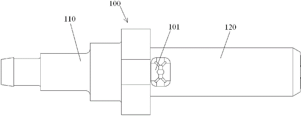
The invention discloses a manufacture method of an insertion core device of a fiber connector. The manufacture method comprises that an insertion core assembly is provided; a fiber is inserted into a fiber jack of the insertion core assembly till the fiber is protruded out of the front end of the insertion core assembly for a preset distance; and an adhesive is filled into the insertion core assembly so that the adhesive can flow into the fiber jack, and after the adhesive is solidified, the fiber can be kept in a proper position in the fiber jack. According to the invention, the fiber can be smoothly inserted into the insertion assembly without damage, and the adhesive is not adhered to the part, protruded out of the front end of the insertion core assembly, of the fiber.

Description

technical field [0001] The invention relates to a ferrule device of an optical fiber connector and a manufacturing method of the ferrule device. Background technique [0002] Figure 1a shows a schematic diagram of a conventional single core ferrule assembly 10 for manufacturing fiber optic connectors; and Figure 1b shown Figure 1a A cross-sectional view of the single core ferrule assembly 10 is shown. [0003] Such as Figure 1a and Figure 1b As shown, at present, in the manufacturing process of single-core optical fiber connectors, the commonly used ferrule assembly 10 includes a ferrule 12 and a tail handle 11 connected to the rear end of the ferrule 12 . The ferrule tail handle 11 can be a plastic part formed on the rear end of the ferrule 12 by injection molding, or can be a metal part fixed on the rear end of the ferrule 12 by crimping. [0004] Such as Figure 1a and Figure 1b As shown, a housing cavity 14 for accommodating adhesive is formed in the ferrule ta...

Claims


Application Information

Patent Timeline
Patent Type & Authority Applications(China)
IPC IPC(8): G02B6/38
CPCG02B6/3834G02B6/3861G02B6/4471G02B6/3821G02B6/3881G02B6/3882G02B6/3898
Inventor 童朝阳林麟刘蕾
Owner TYCO ELECTRONICS (SHANGHAI) CO LTD
Learn More