Dry steam cabinet furnace

A dry steam and steaming cabinet technology, applied in the field of kitchen utensils, can solve the problems of affecting the original taste of food, long heating time, bad taste of food, etc., and achieve the effect of rational use of space, uniform steam, and improvement of space utilization rate.

Inactive Publication Date: 2016-02-24
FUZHOU RONGKUN KITCHEN EQUIP
View PDF6 Cites 3 Cited by
  • Summary
  • Abstract
  • Description
  • Claims
  • Application Information

AI Technical Summary

Problems solved by technology

There is water in the steam of the existing steam cabinet furnace, and the steam generated by the boiling state of water will inevitably carry ungasified water. When there is no resistance at the gas outlet, the water is easily carried out by the steam. Such water vapor It contains less heat and needs to be heated for a long time. At the same time, the water contained in the water vapor penetrates into the heated food, affecting the original taste of the food, and causing the water in the water tank to lose quickly. It needs to be constantly replenished with cold water, which consumes a lot of energy. But keep adding cold water to the water tank to stop the boiling, causing the amount of steam to increase and decrease during the heating process, and the cooked food tastes bad.

Method used


Image

  • Dry steam cabinet furnace
  • Dry steam cabinet furnace
  • Dry steam cabinet furnace

Examples


Embodiment 1

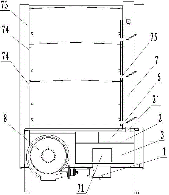
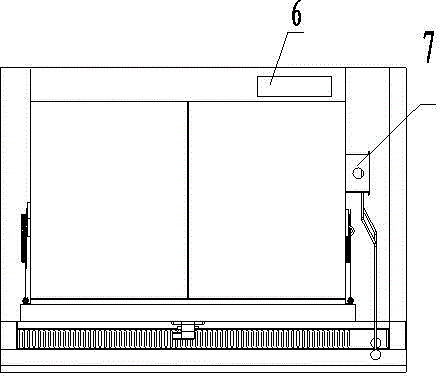
[0038] Example 1, such as Figure 3-8As shown, the present invention is improved on the basis of the existing steaming cabinet furnace, which is the same as the existing steaming cabinet furnace, consisting of a steaming cabinet above and a furnace body below, specifically it also includes a burner 1 , water tank 2, furnace 3, exhaust flue 6, steam cabinet 9, burner head 1 is positioned in the furnace 3, and the front end of furnace 3 has a fire viewing port 31, and the water tank is an airtight water tank, and the difference is that the flue exhaust 6 and the water tank The gas outlets of 2 are combined together, and the flue exhaust duct is changed from the back of the furnace 3 to the side. In the case of the same overall width, the width of the water tank and the furnace 3 can be increased, and the use of space can be effectively and rationally used to improve space utilization. The side edge of the upper surface of the water tank 2 has an opening 26 that can pass through...

Embodiment 2

[0041] Example 2, such as Figure 9-11 As shown, a further improvement is made on the basis of Embodiment 1. A water inlet chamber 5 is designed below the furnace 3. The upper surface of the water inlet chamber 5 and the lower surface of the water tank 2 form a closed furnace 3, and the mixed gas is blown by the fan. 8 drives into the burner head 1 to burn, the outlet pipe 65 of the flue passage water chamber is connected with the water inlet chamber 5, and the water inlet chamber 5 is replenished by the water outlet pipe 65, and there is a drain valve 51 under the water inlet chamber 5, which can be used for cleaning Or drain water when changing water. A heat absorbing pipe 4 is designed in the furnace 3, and the two ends of the heat absorbing pipe 4 are respectively connected with the water inlet chamber 5 and the water tank 2, and the side wall of the furnace 3 has a water replenishment channel 32 connecting the water tank 2 and the water inlet chamber 5, and the water repl...


PUM


Abstract

The invention belongs to cooking utensils especially steam cabinet furnaces and particularly relates to a dry steam cabinet furnace. The dry steam cabinet furnace comprises a furnace end, a water tank, a hearth, a discharge flue and a steam cabinet, wherein the furnace end is located in the hearth, a fire observation opening is formed in the front end of the hearth, and the water tank is airtight. The dry steam cabinet furnace is characterized in that the side edge of the upper surface of the water tank is provided with an opening allowing the discharge flue to penetrate, an interval is formed between the outer wall of the discharge flue and the opening of the water tank and is a steam outlet of the water tank, baffles are arranged on the periphery of the interval to form a steam chamber, and a steam outlet is formed in the surface of the steam chamber and is connected with a steam pipe. The dry steam cabinet furnace has the advantages that generated steam is high in temperature and dry and contains a large amount of heat, the heating time of food is shortened, and the original flavor of the food can be kept at the same time; heat absorption area is large, heat efficiency is high, steam amount is stable and continuous, the temperature of exhausted smoke is low, the taste of the cooked food is good, and the original flavor of the food is kept more easily.

Description

technical field [0001] The invention belongs to kitchen utensils, in particular to a steamer oven. Background technique [0002] Most of the existing steaming cabinet furnaces can be divided into: the upper steaming cabinet and the lower furnace body, specifically as figure 1 As shown, it consists of burner head 1, water tank 2, furnace 3, flue exhaust duct 6, steam cabinet 9, etc. burner head 1 is located in furnace hearth 3, and the front end of furnace hearth 3 has a fire viewing port 31, and flue exhaust duct 6 is in the steam cabinet The water tank 2 is an airtight water tank with a water inlet pipe communicating with the water tank 2, an air outlet 21 connected with the steam pipe 7 on the side edge of the upper surface of the water tank, and a through hole 75 connected with the steam pipe 7 in each layer of the steaming cabinet. 7 are communicated with each other, and the through hole 75 is controlled by a switch. There is an overflow hole 74 above the steam cabinet ...

Claims


Application Information

Patent Timeline
Patent Type & Authority Applications(China)
IPC IPC(8): A47J27/16
Inventor 林巧林坤林宝蓉
Owner FUZHOU RONGKUN KITCHEN EQUIP
Why Eureka
Try Eureka