Normal measurement and adjustment method for drilling of free-form surface of aviation thin-wall piece

A kind of thin-walled parts, aviation technology, applied in the field of measurement and adjustment, can solve the problems of low measurement accuracy, poor precision, unpredictable shape of aviation thin-walled parts, etc.

Active Publication Date: 2016-02-24
SHANGHAI TOPNC NUMERICAL CONTROL TECH CO LTD
View PDF8 Cites 11 Cited by
  • Summary
  • Abstract
  • Description
  • Claims
  • Application Information

AI Technical Summary

Problems solved by technology

However, due to the local weak rigidity and easy clamping deformation of thin-walled parts, these characteristics make the shape of aviation thin-walled parts unpredictable during the hole making process. How to measure and adjust the normal direction with high efficiency and high precision has always been an important part of the assembly and manufacturing process. in the puzzle
At present, the normal direction guarantee of the manual hole mainly adopts the drilling mold, which is inefficient
Most of the normal measurement of automatic hole making adopts the method of point laser approximate plane fitting to find the normal direction. This method has low measurement accuracy and is susceptible to environmental interference.
In addition, normal direction adjustment is currently mainly adjusted through 6-DOF industrial robots and offline programming, which has disadvantages such as poor precision and low efficiency.

Method used


Image

  • Normal measurement and adjustment method for drilling of free-form surface of aviation thin-wall piece
  • Normal measurement and adjustment method for drilling of free-form surface of aviation thin-wall piece
  • Normal measurement and adjustment method for drilling of free-form surface of aviation thin-wall piece

Examples


Embodiment 1

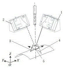
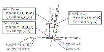
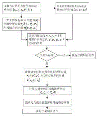
[0031] see Figure 1-3 , in an embodiment of the present invention, a method for measuring and adjusting the normal direction of a free-form surface of an aviation thin-walled part, which includes the following steps:

[0032] 1) Set one non-contact 2D laser sensor on both sides of the tool on the side of the aviation thin-walled part to be drilled, respectively, 2D laser sensor A1 and 2D laser sensor B2, and the emitted light of the two 2D laser sensors is respectively projected After arriving at the surface of the aviation thin-walled part, two intersecting laser stripes are formed, namely laser stripe A3 and laser stripe B4. The intersection point of the laser stripe is the drilling position on the surface of the aviation thin-walled part, and the axis extension line of the tool passes through the point of intersection, ie figure 1 Middle drill point / laser stripe intersection 5 is shown.

[0033] 2) Read the machine tool motion coordinates of the current drilling point / la...


PUM


Abstract

The invention discloses a normal measurement and adjustment method for drilling of the free-form surface of an aviation thin-wall piece. The method includes the following steps that a numerical control system of a machine tool reads the machine tool motion coordinates of a current drilling point location; the current position vector of a tool tip and the current direction vector of a tool shaft in a workpiece coordinate system are calculated through changes of the machine tool motion coordinates; the normal is obtained through multiplication cross of the tangent vector of the crosspoint of two space curves of the surface of the aviation thin-wall piece, namely the actual normal of the drilling point location of the workpiece is obtained; and the included angle between the current drilling direction and the actual normal of the current drilling point location of the aviation thin-wall piece is worked out, the posture of a tool or the aviation thin-wall piece needs to be adjusted when the value of the included angle is beyond the range required by the aviation manufacturing standard, and the normal drilling operation is conducted after adjustment is completed. Measurement station switchover is not needed, and the normal detection and the tool tip distance detection are completed through one-time measurement before drilling. The normal measurement and adjustment method has the advantages that the measurement accuracy is high, the application range is wide, and the measurement and adjustment efficiency is high.

Description

technical field [0001] The invention relates to the technical field of measurement and adjustment, in particular to a normal measurement and adjustment method for drilling free-form surfaces of aviation thin-walled parts. Background technique [0002] As we all know, aviation thin-walled parts such as aircraft fuselage skins and wings have the characteristics of light weight and good overall structural rigidity. Aviation thin-walled parts require a large number of holes, and the normal verticality of the holes made by aviation thin-walled parts has a great impact on structural parts. have a significant impact on the fatigue performance. However, due to the local weak rigidity and easy clamping deformation of thin-walled parts, these characteristics make the shape of aviation thin-walled parts unpredictable during the hole making process. How to measure and adjust the normal direction with high efficiency and high precision has always been an important part of the assembly an...

Claims


Application Information

Patent Timeline
Patent Type & Authority Applications(China)
IPC IPC(8): B23Q17/24G06F19/00
CPCB23Q17/24G16Z99/00
Inventor 刘钢
Owner SHANGHAI TOPNC NUMERICAL CONTROL TECH CO LTD
Why Eureka
Try Eureka