Flocculant feeding device

A technology of feeding device and flocculant is applied in the field of feeding device, which can solve the problems of poor thermal conductivity of powder, influence processing, poor sealing performance of the outlet, etc., and achieve the effect of ensuring long-term drying, simple and reliable structure, and good sealing performance.

Active Publication Date: 2016-02-24
苏州依斯倍环保装备科技有限公司
View PDF7 Cites 10 Cited by
  • Summary
  • Abstract
  • Description
  • Claims
  • Application Information

AI Technical Summary

Problems solved by technology

[0002] At present, the feeding device of the polymer powder flocculant dosing machine in the wastewater treatment industry generally adopts a screw feeder. Falling into the mixing tank, because the screw pitch and length of the existing screw feeder are small, the general disadvantages are: 1. The resistance of the feeder is relatively large, the outlet is poorly sealed, and the flocculant powder is easily damp and agglomerated
2. After agglomeration, the colloidal powder adheres to the screw, reducing the feeding speed or even completely blocking the feeding port, resulting in inaccurate dosage and affecting subsequent processing
3. At the same time, due to the sealing of the upper powder storage box, the powder flocculant is also prone to moisture and agglomeration
[0003] At present, the way to solve the problem of the above-mentioned flocculants being susceptible to moisture and agglomeration is generally to wind a heating wire on the nozzle outside the screw, hoping to remove the water by heating. However, since the water inside the powder does not touch the atmosphere, Not easy to volatilize; at the same time, the powder has poor thermal conductivity and the heating time is too short, so the effect is not ideal

Method used


Image

  • Flocculant feeding device
  • Flocculant feeding device

Examples


Embodiment 1

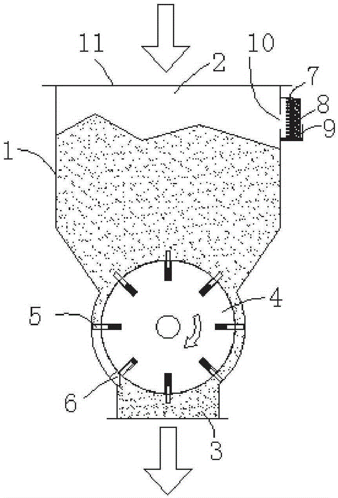
[0034] Such as figure 1 As shown, a flocculant feeding device disclosed in Example 1 of the present invention includes a silo 1, an impeller rotor, and a refrigeration dehumidification device. The top of the silo 1 is provided with a feeding port 2, and the bottom is provided with a discharge port. 3. A transparent plexiglass cover plate 11 is provided on the feeding port 2 . The impeller rotor is arranged in the silo 1 and is located near the discharge port 3 . When the impeller rotor is not rotating, it blocks the discharge port 3; when it rotates clockwise, the material is discharged with the rotation of the impeller rotor.

[0035] In Embodiment 1, the impeller rotor includes a rotor 4 and eight blades 5 evenly distributed on the outer circumference of the rotor 4 , and the blades 5 are connected to the rotor 4 through springs. A scraper 6 is arranged on the inner wall of the silo near the discharge port 3 , and when the rotor 4 rotates, the scraper 6 can contact the bla...

Embodiment 2

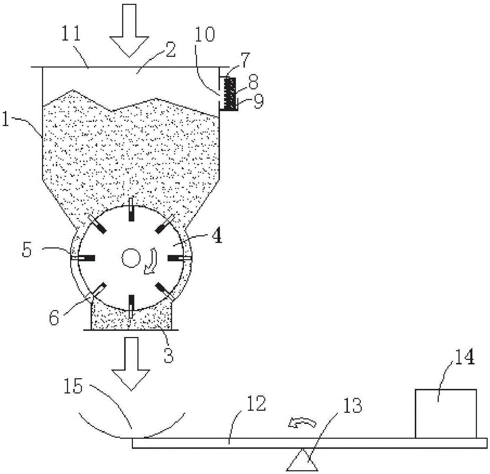
[0039] Such as figure 1 As shown, different from the structure of a flocculant feeding device disclosed in Example 1, the number of blades 5 on the rotor 4 in Example 2 is set to 16, and a Set up a weighing device to automatically tilt and feed when the preset weight is reached. The 16 elastic blades 5 can control the feeding more finely, combined with the weighing device at the bottom, the feeding amount can be controlled more precisely. Embodiment 2 is applicable to occasions requiring precise feeding. For other structures and working principles, refer to the introduction in Embodiment 1 above, and will not be repeated here.


PUM


Abstract

The invention discloses a flocculant feeding device which includes a bin, an impeller rotor and a cooling dehumidification device, wherein a feeding hole is formed in the top of the bin; a discharge outlet is formed in the bottom of the bin; the impeller rotor is arranged in the bin, and when the impeller rotor does not rotate, the discharging outlet is blocked by the impeller rotor, and when the impeller rotor rotates, the impeller rotor drives the material to be discharged; the cooling dehumidification device is installed on the side wall, close to the feeding hole, of the bin and comprises an evaporator, a refrigeration chip and a water absorption layer. The refrigeration chip cools the air in the bin via the evaporator, and the water absorbing layer adsorbs the cooled water and discharges the water out of the bin. The flocculant feeding device has good seal performance, ensures the drying of a flocculant, reduces the agglomeration phenomenon caused by damp, can still run normally after affected with damp to further guarantee the accuracy of the dose of the flocculant, and is simple and reliable in structure.

Description

technical field [0001] The invention relates to a feeding device, in particular to a flocculant feeding device. Background technique [0002] At present, the feeding device of the polymer powder flocculant dosing machine in the wastewater treatment industry generally adopts a screw feeder. Falling into the mixing tank, because the screw pitch and length of the existing screw feeder are all small, the general disadvantages are: 1. The feeder resistance is relatively large, the outlet seal is poor, and the flocculant powder is easily damp and agglomerated. 2. After agglomeration, the colloidal powder adheres to the screw, reducing the feeding speed or even completely blocking the feeding port, resulting in inaccurate dosage and affecting subsequent processing. 3. At the same time, due to the sealing of the upper powder storage box, the powder flocculant is also prone to moisture and agglomeration. [0003] At present, the way to solve the problem of the above-mentioned flocc...

Claims


Application Information

Patent Timeline
Patent Type & Authority Applications(China)
IPC IPC(8): B65D88/68B65D88/74B65G65/48
CPCB65D88/68B65D88/747B65G65/48
Inventor 王人松
Owner 苏州依斯倍环保装备科技有限公司
Why Eureka
Try Eureka