Wave-energy generating device

A power generation device and wave energy technology, applied to ocean energy power generation, engine components, machines/engines, etc., can solve problems such as high cost, difficult maintenance, complex structure, etc., and achieve low environmental impact, easy maintenance and replacement, and manufacturing accuracy less demanding effect

Inactive Publication Date: 2016-02-24
SHANDONG UNIV
View PDF8 Cites 15 Cited by
  • Summary
  • Abstract
  • Description
  • Claims
  • Application Information

AI Technical Summary

Problems solved by technology

Other wave energy generating devices have comple

Method used


Image

  • Wave-energy generating device
  • Wave-energy generating device
  • Wave-energy generating device

Examples


Embodiment 1

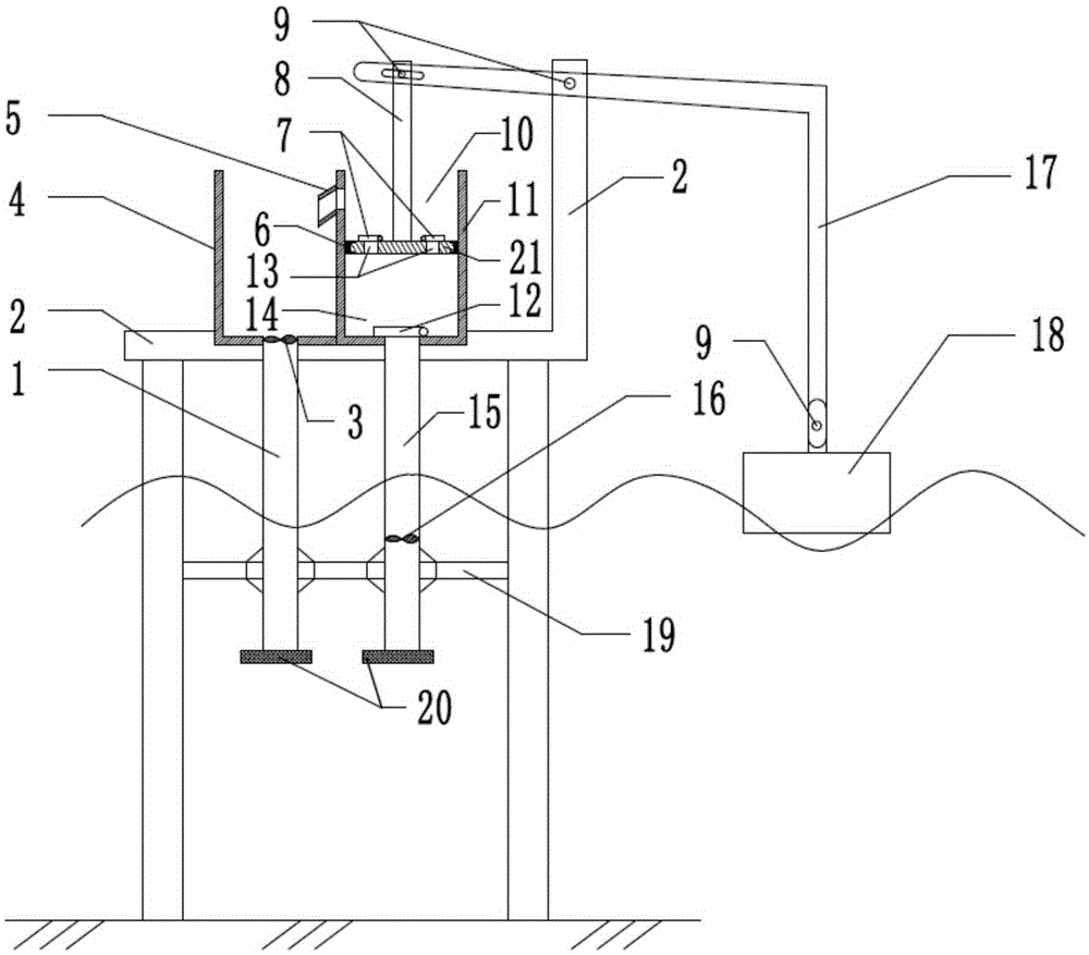
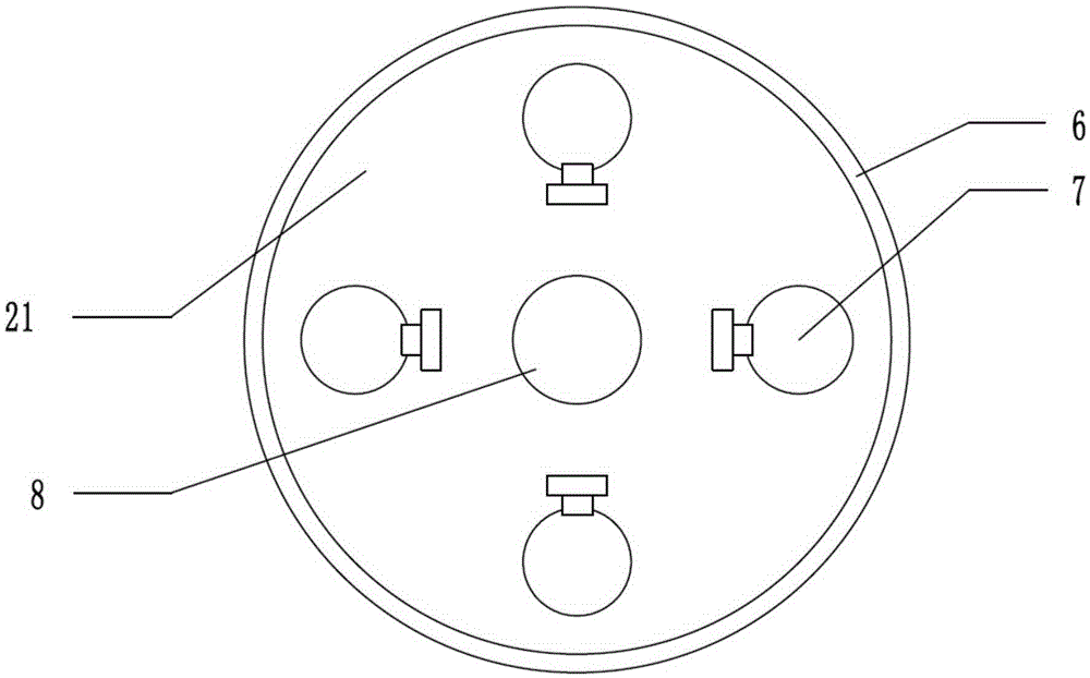
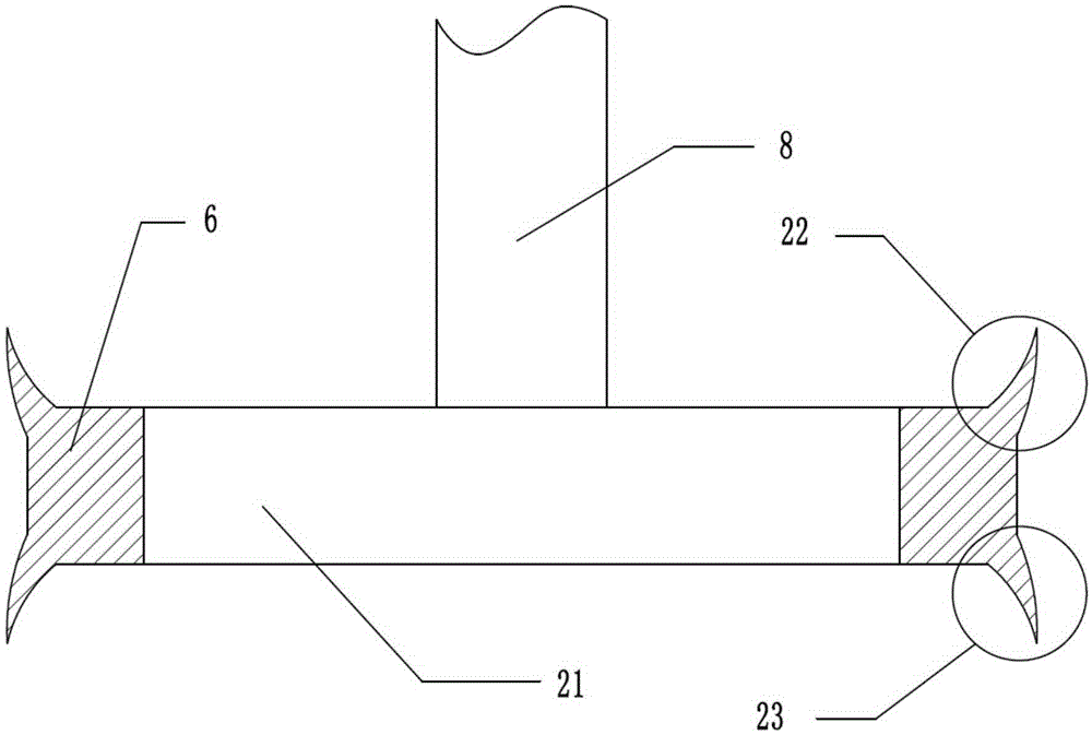
[0022] combine figure 1 , for a single invention device description: the floating block 18 is hinged by the pin 9 and the pressure rod 17, and floats on the sea surface, the pressure rod 17 is hinged by the pin 9 and the support platform 2, and the bar-shaped hole of the pressure rod is passed by the pin 9 and The piston rod 8 forms a sliding connection. There are pin holes in the middle part and both ends of the pressure bar, and the distance from the pin hole in the middle part of the pressure bar to the floating block is twice the distance from the bar hole. The piston rod 8 and the piston 21 are fixedly connected, the upper rubber sheet 22 and the lower rubber sheet 23 are provided around the sealing ring 6, the piston 21 slides and seals with the water suction cylinder 11 through the sealing ring 6, and there are four piston drain ports 13 on the piston 21. Piston hinged baffle switch 7 is installed at piston outlet 13, water suction cylinder 11 is fixed on support platf...

Embodiment 2

[0030] Piston sealing ring 6 uses hydraulic cylinder special sealing ring. Suction cylinder 11 is an open piston cylinder. Others are the same as embodiment one.

Embodiment 3

[0032] Suction pipe hydraulic turbine power generation device 16 is installed below the waterline of water suction pipe 15, and the distance from the sea surface is three times of the measured wave height. The water suction pipe 15 and the discharge pipe 1 are in contact with seawater, and the distance from the sea surface is three times the wave height. Others are the same as embodiment one.


PUM


Abstract

The invention belongs to the field of utilization of renewable energy, and provides a wave-energy generating device for generating power through water potential energy. The device comprises a water absorbing tank, a water storing tank, a water absorbing pipe, a water draining pipe, a piston, a sealing ring, a floating block, a hinge pin, a supporting platform, and a water draining port in the upper part of the water absorbing tank. The device is characterized by further comprising a pressing rod, a turbine generating device in the water absorbing pipe, a turbine generating device in the water draining port, a baffle switch hinged to the piston, a baffle switch hinged to the water absorbing port, a filtering net and a water pipe fixing rack, wherein the pressing rod and a rack achieve a lever effect, and the floating force and gravity effect of the wave to the floating block can be amplified to act to the piston. According to the water-energy generating device, the pressing rod can drive the piston to reciprocate, and the baffle switch hinged to the piston and the baffle switch hinged to the water absorbing port play supporting roles, so as to achieve the purposes of absorbing water and draining water; meanwhile, the turbine generating devices in the water absorbing pipe and the water draining port of the water storing tank are correspondingly driven to generate power during the water absorbing process and the water draining process; array manners are combined to use, so that the wave energy can be utilized well, and the purpose of continuously generating power can be achieved. The device is of an opening structure, is influenced a little by the environment, and is simple in structure, and convenient to maintain and replace a part.

Description

technical field [0001] The invention belongs to the field of renewable energy utilization, and relates to a wave energy generating device for generating electricity by using seawater potential energy. Background technique [0002] Compared with other marine energy sources, wave energy has the advantages of wide distribution, high energy flow density, and easy conversion of energy forms. It attracts skilled craftsmen from all over the world and tries to convert it for human use. The existing wave energy conversion devices are mainly wave energy storage type, valve type, point absorption type, pendulum type and so on. The types of wave energy generating devices that have been put into use are mainly wave-condensing and valve-type. The Chinese patent with the patent number CN200710124322.7 proposes a device for converting wave energy into potential energy of seawater. It is pressed into the high-level water reservoir by a closed hydraulic cylinder. Its float is directly conn...

Claims


Application Information

Patent Timeline
IPC IPC(8): F03B13/22
CPCF03B13/22F05B2220/706Y02E10/30
Inventor 刘延俊罗华清张健薛钢张伟张募群贾瑞丁洪鹏刘科显丁梁锋
Owner SHANDONG UNIV
Why Eureka
Try Eureka